Vacuum Systems
Vacuum Chambers
Flanges & Components
Vacuum Valves
Vacuum Pumps
Vacuum Fluids
Traps & Filters
Evaporation Sources
Evaporation Materials
Sputter Targets
Deposition Sources
Electrical Feedthroughs
Manipulation & Motion
Gas & Liquid Mgmt
Process Equipment
Pressure Measurement
System Components
 
Great Buys!!
Sales & Promotions
Flanges & Components  >  QF (KF) >  QF Flanges >  ISO >  ISO Flanges > 

ISO Flanges

Technical Notes

ISO flanges conform to the vacuum flange standards issued by the International Standards Organization (ISO). They share the same underlying principle as the QF (KF or NW) flange series in that two smooth-faced sexless flanges clamp together with a sealing device between them. Each flange face has a counter-bore into which fits a metal Centering Ring with an elastomeric O-ring around its outer diameter. The centering ring has two roles: first to align the flanges; and second to prevent the O-ring being pushed in by the external atmospheric pressure when the joint is under vacuum.

ISO 
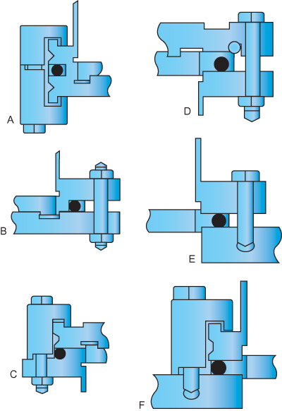
flanges have two clamping mechanisms holding the flanges together. The first, called K-style, uses separate clamps hooked over the outer edge of the mating flanges and spaced around the circumference. The second, called F-style, uses conventional bolt holes in the flange periphery. While an F-style flange comes as a single, solid part complete with bolt holes, it is also available, and more commonly used, in a three part structure in which a K-style flange is adapted with a retaining ring and a bolt ring into the F-style (see diagrams below). The multi-part flange has the obvious advantage that it mates to either K-style or F-style simply by using the appropriate pieces in the assembly. The single part F-style, however, also has an important advantage, though a less obvious one. It has more strength than the multi-part flange when used as a structural element to support the weight of the vacuum system.

K-style flanges are usually less expensive than the F-style and require less clearance around the tubing during insulation. But we offer a variety of bolt/clamp options permitting joints between mixed K- and F-style flanges The illustration (see diagram below) shows various clamping arrangements. Note: the composite does not try to depict a practical arrangement of flanges.
Figure 1 (ISO Flange Clamping Arrangements)
 
Fig A   Double claw clamp attaching two K-style flanges
     
Fig B   Bolt and nut fastener for two F-style flanges
     
Fig C   Clamp to bolt fastener for K-style to F-style connection
     
Fig D   Bolt and nut fastener for K-style bolt ring to F-style
     
Fig E   Stud and nut fastener for F-style flange to a blind tapped mating flange
     
Fig F   Claw clamp with screw fastener for K-style to a blind tapped mating flange


K-style Flange/Clamp Dimensions

Size Tube
OD
in.
Flange
OD
in. (mm)
Flange
Thick.
in. (mm)
Single Clamps Double
Clamps
No. of
Clamps
Ass'bly
Dia.
in. (mm)
Height
in. (mm)
Thread Height
in. (mm)
Min. Opt.
ISO 63 2 1/2 3.74 .472 1.2 5/16-18 1.98 3 4 5.00
  (95) (12) (30) (M8) (50)

(127)
ISO 80 3 4.33 .472 1.2 5/16-18 1.98 4 8 5.59
  (110) (12) (30) (M8) (50)

(142)
ISO 100 4 5.12 .472 1.2 5/16-18 1.98 4 8 6.38
  (130) (12) (30) (M8) (50)

(162)
ISO 160 6 7.09 .472 1.25 5/16-18 2.05 4 8 8.35
  (180) (12) (32) (M10) (52)

(212)
ISO 200 8 9.45 .472 1.25 5/16-18 2.05 6 12 10.71
  (240) (12) (32) (M10) (52)

(272)
ISO 250 10 11.42 .472 1.25 5/16-18 2.05 6 12 12.68
  (290) (12) (32) (M10) (52)

(322)
ISO 320 12 3/4 14.57 .670 1.57 7/16-14 2.56 8 12 16.73
  (370) (17) (40) (M12) (52)

(425)
ISO 400 16 17.72 .670 1.57 7/16-14 2.56 8 16 20.08
  (450) (17) (40) (M12) (52)

(510)
ISO 500 20 21.65 .670 1.57 7/16-14 2.56 12 16 24.02
  (550) (17) (40) (M12) (52)

(610)
ISO 630 24 27.17 .866 1.77 7/16-14 3.35 14 18 29.53
  (690) (22) (45) (M12) (85)     (750)

F-style Flange/Bolts Dimensions

Flanges Holes Bolts
Size OD
in. (mm)
Thick.
in. (mm)
No. Dia.
in. (mm)
BCD
in. (mm)
Dia.
in. (mm)
Wrench
in. (mm)
ISO 63 5.12 .47 4 .35 4.33 5/16 1/2
  (130) (12)
(9) (110) (8) (13)
ISO 80 5.71 .47 8 .35 4.92 5/16 1/2
  (145) (12)
(9) (125) (8) (13)
ISO 100 6.50 .47 8 .35 5.71 5/16 1/2
  (165) (12)
(9) (145) (8) (13)
ISO 160 8.86 .63 8 .43 7.87 3/8 9/16
  (225) (16)
(11) (200) (10) (17)
ISO 200 11.22 .63 12 .43 10.24 3/8 9/16
  (285) (16)
(11) (260) (10) (17)
ISO 250 13.19 .63 12 .43 12.20 3/8 9/16
  (335) (16)
(11) (310) (10) (17)
ISO 320 16.73 .79 12 .55 15.55 1/2 3/4
  (425) (20)
(14) (395) (12) (19)
ISO 400 20.08 .79 16 .55 18.90 1/2 3/4
  (510) (20)
(14) (480) (12) (19)
ISO 500 24.02 .79 16 .55 22.83 1/2 3/4
  (610) (20)
(14) (580) (12) (19)
ISO 630 29.53 .95 20 .55 28.35 1/2 3/4
  (750) (24)
(14) (720) (12) (19)

Centering Ring Dimensions

Size Lip
OD
in. (mm)
Lip
ID
in. (mm)
Thick.
in. (mm)
ISO 63 2.756 2.63 .154
  (70) (66.8) (3.9)
ISO 80 3.268 3.14 .154
  (83) (79.8) (3.9)
ISO 100 4.016 3.89 .154
  (102) (98.8) (3.9)
ISO 160 6.024 5.90 .154
  (153) (149.9) (3.9)
ISO 200 8.386 8.26 .154
  (213) (209.8) (3.9)
ISO 250 10.276 10.14 .154
  (261) (257.6) (3.9)
ISO 320 12.520 12.30 .220
  (318) (312.4) (5.6)
ISO 400 15.748 15.53 .220
  (400) (394.5) (5.6)
ISO 500 19.724 19.51 220
  (501) (495.6) (5.6)
ISO 630 25.630 25.41 .220
  (651) (645.4) (5.6)
 
 
  Vacuum SystemsVacuum ChambersFlanges & ComponentsVacuum ValvesVacuum PumpsVacuum FluidsTraps & FiltersEvaporation MaterialsEvaporation SourcesSputter TargetsSputter SourcesIon SourcesElectrical FeedthroughsManipulation & MotionGas & Liquid Mgmt.Re-Circulating ChillersProcess InstrumentsPressure MeasurementSystem Components


Copyright © 1996-2006 Kurt J. Lesker Company. All rights reserved.
And now for the ubiquitous small print:   Website Terms of Use and Legal Notices      Standard Terms & Conditions of Sale      Trademarks