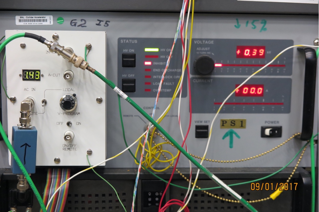
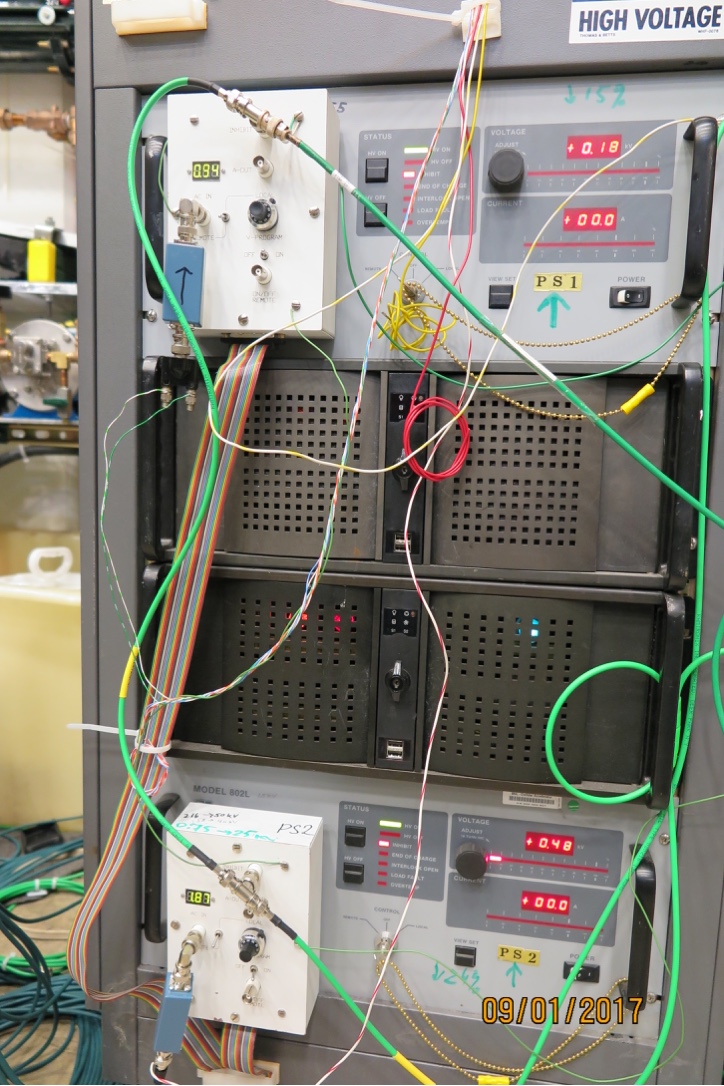
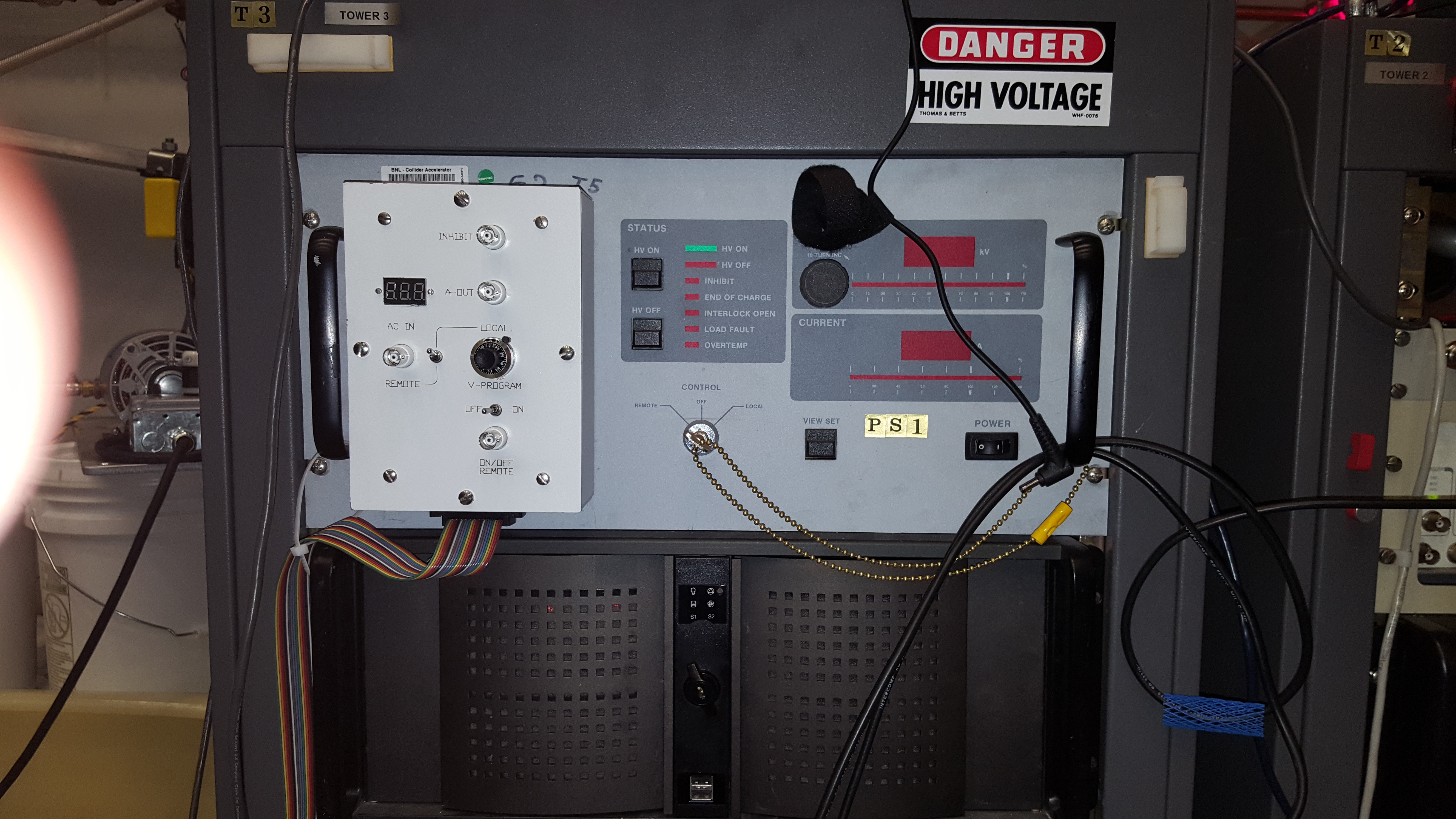
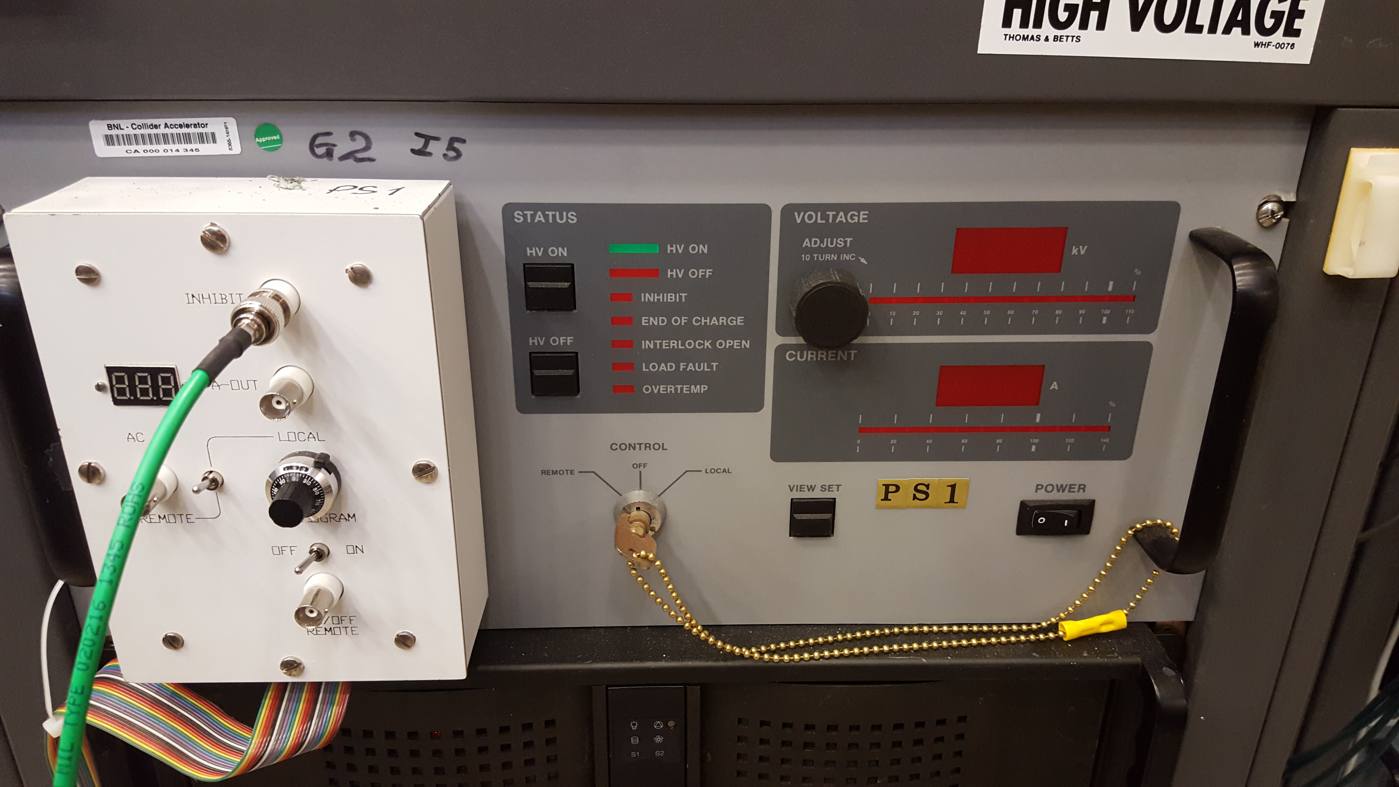
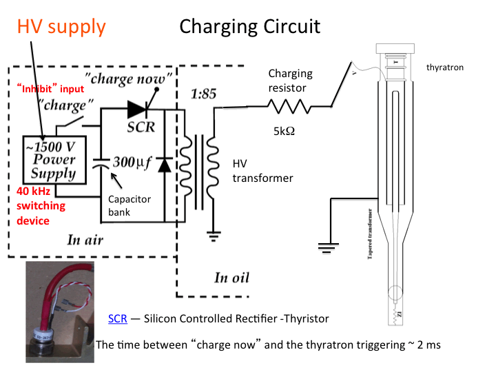
The HV supply charges a capacitor bank in the
Primary Charging Supply to approximatlely 700V.
The capcitor bank is discharged throught the
HV transformer when the thyristor in the charging supply
is triggers. The transformer radtio of the HV transformer is 85, so the voltage on the secondary, and the Blumlein, is 60kV.
The connection between the HV supply and the Primary Charging Supply is open (inhibited) by the
Control Circuit when the Blumlein is discharged.
(See section 6.4 of manual) First check for obvious trouble such as input power, output connections, control connections and signal levels.
In particular, the interlock, the INHIBIT and the ON/OFF signals. If there is no load connected, the power supply will sense an open crircuit and immediately shut down indicating a LOAD FAULT.
IF there is a short circuit or orverload condition on the output, the power supply will operate in a 50% duty cycle protection mode and indicate a LOAD AULT.
An overload condition can occur if the INHIBIT signal is missing and the discharge rep rate is too high to allow the capacitor to fully charge to V PROGRAM.
- If the power supply is making high voltage but does not appear to be functioning peroperly in a specific application, the probkem may be the applicated related. Consult the EMI Systems customer service department.
- If the power supply is not making high voltage, the problem is usually either fauiled HB output diodes or a problem on a pc board. Refer to the schematics provided in the manual.
- Check the DC bus voltage on the large filter capacitors C1, 2 in the front ot the unit. Should be 250-350 V.
- Check for failed power transistors or diodes on the Inverter Board.
- CHeck the +15V and -5V on the Control Board.
- Check the +12V unregulated at J4-10 If reading zero, check fuses on the Aux Board.
- Check the output and inputs of the main OR-gate U12-1,2,3,4,5. A high level will disable the power supply.
- Check the output of the latches U13-1 and U13-13.
- Check the input to the latche at U12-9,10,11,12.
- Check the V PROGRAM input at U6-8.
- Check the clock at U9-3.
- Check the transistor gate drives at D16,27,28,29 cathode.
