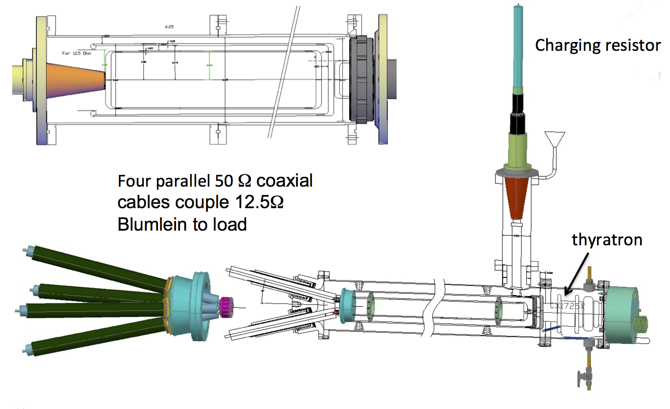
The equivalent circuit of a Blumlein is a pair of coaxial transmission lines in series as shown in Figure a). The switch (T) is the thyratron. The transmission line that is oriented verically and labeled 25(12.5) ohms corresponds to the
4 cables (12.5 Ohm) that couple the Blumlein to the load resistor (12.5ohm) inside the bazooka.
In Figure b) the inner and outer conductors of the second coax are swapped.
In c), the right (second) coax is inserted into the left coax with radii adjusted accordingly.
Final configuration
Another illustration of the topological transformation from series coaxial lines to tri-axial Blumlein from left to right.
Blumlein tri-axial current generator vs conventional Co-axial generator
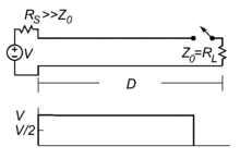
Blumlein pulse generator. In a Blumlein, the voltage at the load (Z) is equal to the charging voltage. The base of the thyratron (switch) is at ground potential. The current through the thyratron is twice the current through the load.
Coaxial transmission line pulse generator. In a conventional coaxial line, the voltage at the load (Z) is 1/2 the charging voltage. The base of the thyratron (switch) is floating with respect to ground.
The current through the thyratron is equal to the current through the load.
Kicker Blumlein
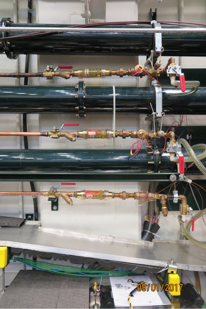
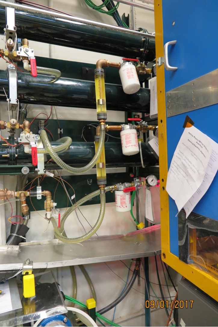
The space between the conductors is filled with castor oil. The pulse width is determined by the length of the line, and the velocity of propagation.
The high dielectric constant of the oil serves to optimize the pulse width, to hold off the high voltage, and to cool the conductors, the charging resistor and the thyratron.
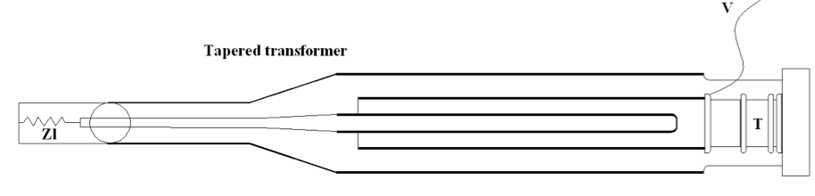
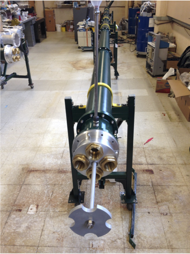
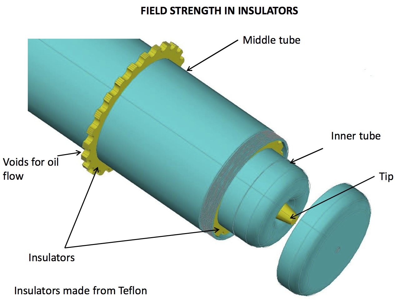
Each Blumlein consists of 3 concentric aluminum cylinders with overall length of about 9m. The upstream end is shown here. The middle of the three tubes is charge to high voltage. The cylinders
are separated by macor collars (not visible). Castor oil circulates between the conductors.
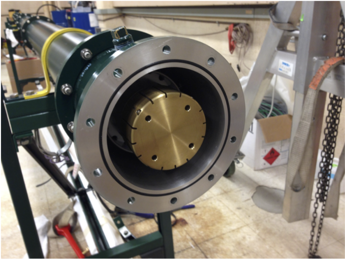
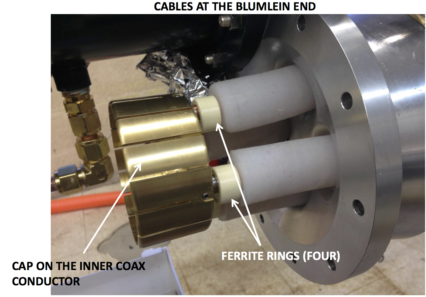
At the downstream end of the Blumlein, the center most conductor is capped (and the middle conductor is not visible).
The four feedthroughs in the cap on the downstream end of the Blumlein connect the central conductor to the 4-50ohm coaxial cables that couple to the load.
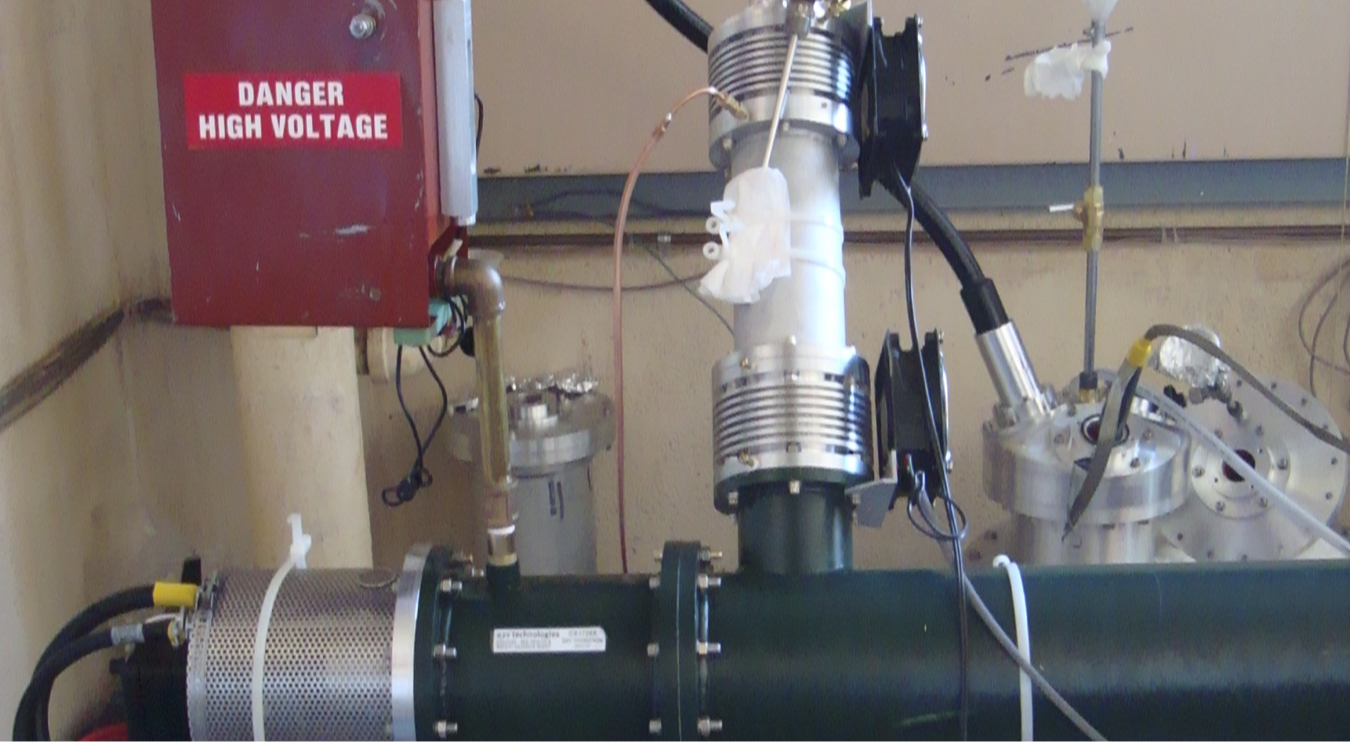
The thyratron and the charging feedthrough are at the far end in this picture.
The middle tuble of the Blumlein is connected to the secondary of the HV transformer through the 5k charging resistor that is inside the upright. The resistor is bathed in the same castor oil
that circulates between the conductors of the Blumlein.
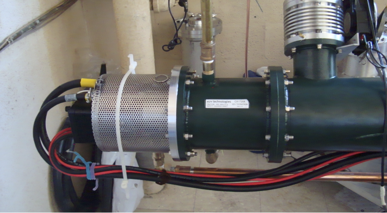
The thyratron is mounted horizontally in the short end section of the outer tube of the Blumlein. It is immersed in the castor oil that fills the spaces between the Blumlein
conductors. The base (cathode) is fixed at ground potential. The anode is coupled to the middle of the Blumlein tubes. Thyratron heater, reservoir, grid bias and triggers
connect through the shielded base.
Cross section and 3 D drawing of Blumlein
The four coaxial cables are terminated in the brass cap that fits over the central conductor at the downstream
end of the Blumlein
#d drawing of upstream end of triaxial line. The center conductor (inner tube) floats at the upstream end. It is isolated from
the end cap by the insulating tip. The middle tube is charged to HV and is connected to the anode of the thyratron.The macor insulators
are not teflon but macor,
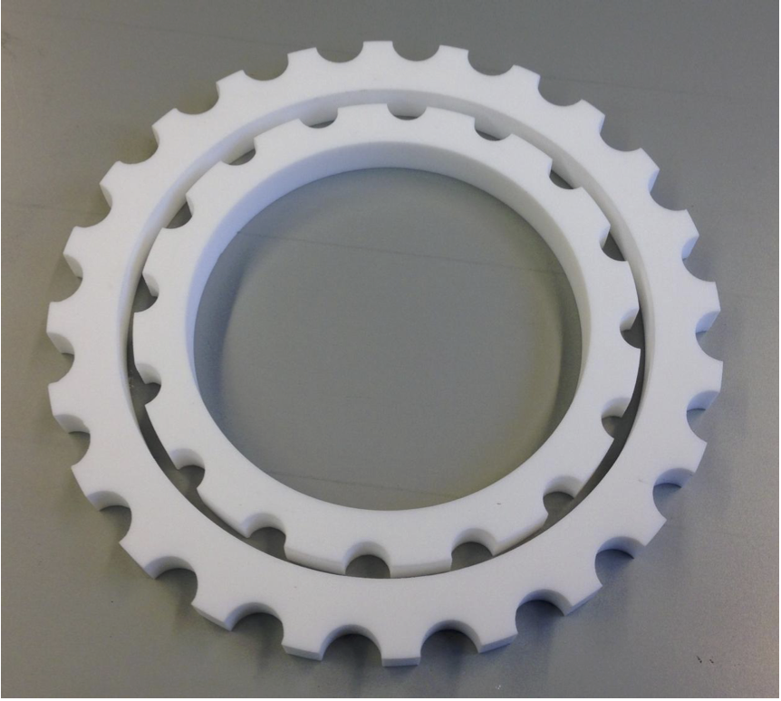
Macor insulators that isolated the three concentric tubes.