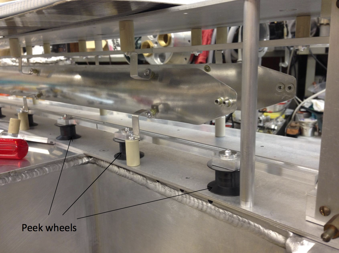
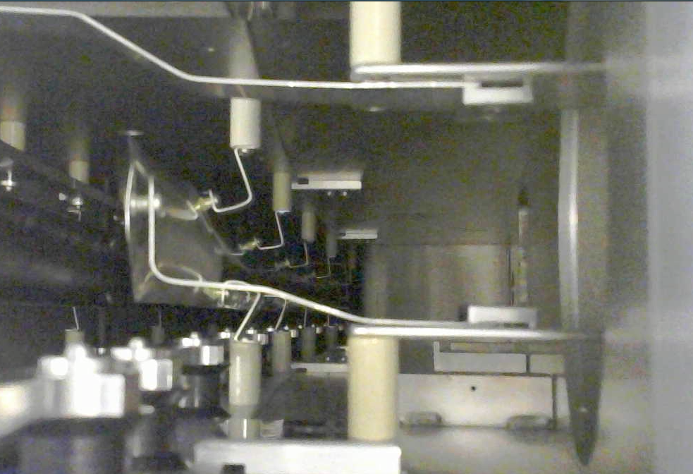
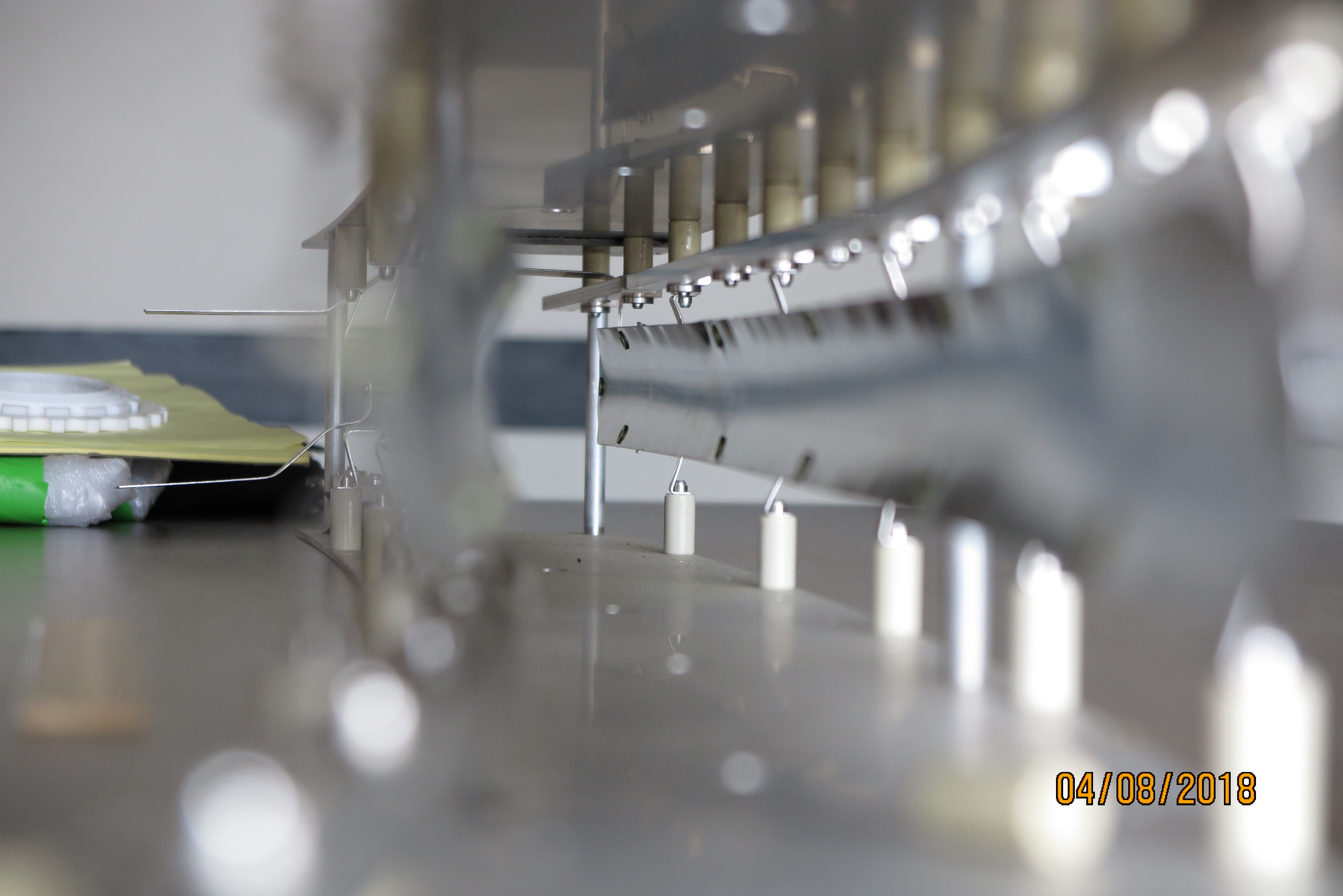
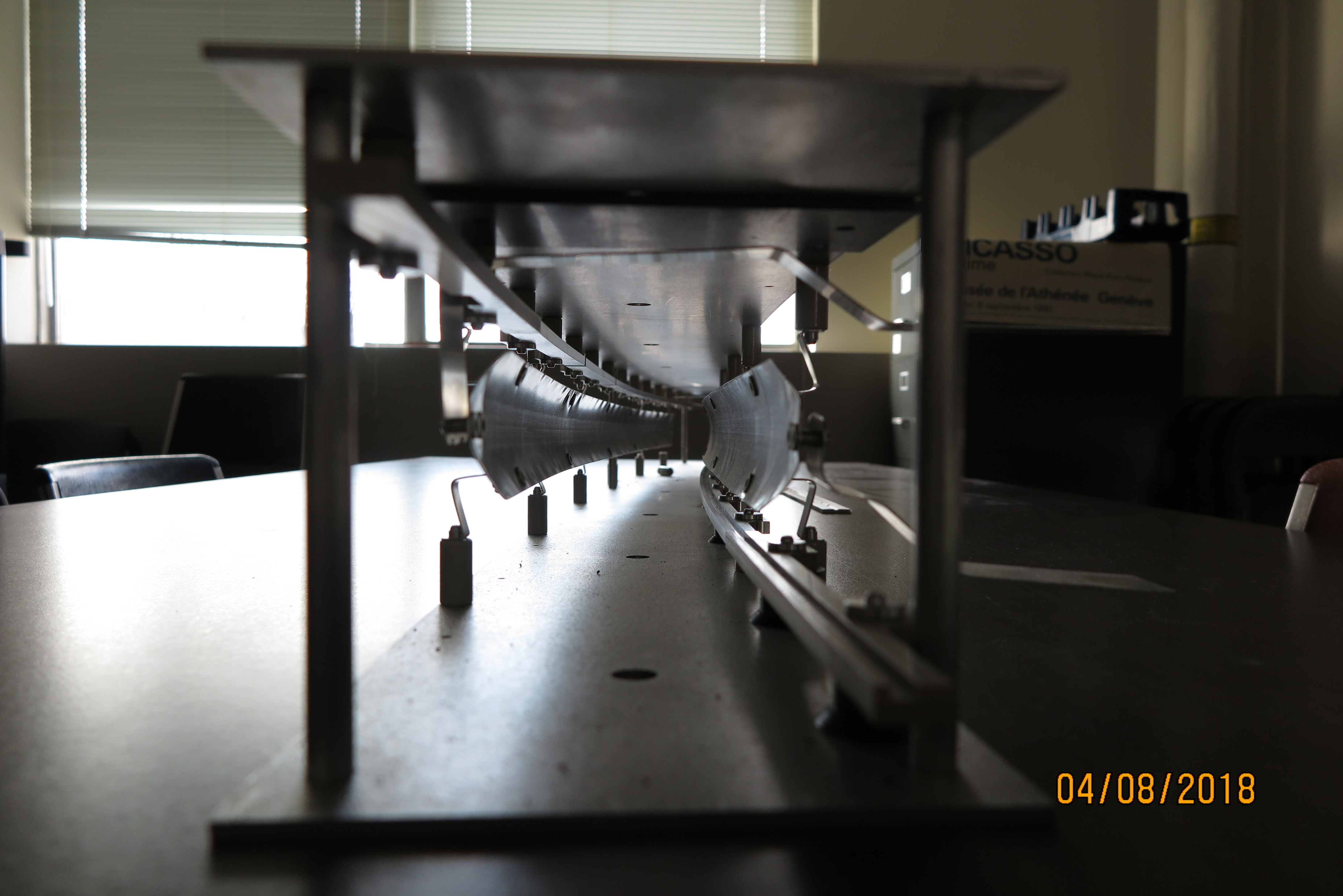
The kicker plates are the shiny curved plates suspended from ceramic standoffs that are mounted to the top and bottom of the "cage" plates. The lower
trolley rail is visible in the photograph as are the peek wheels that guide the trolley cable. The cage is inserted into the vacuum chamber
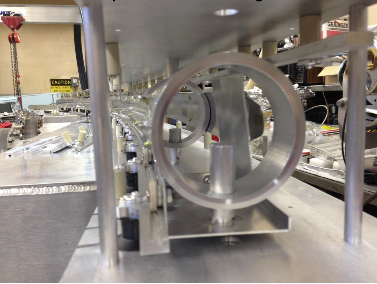
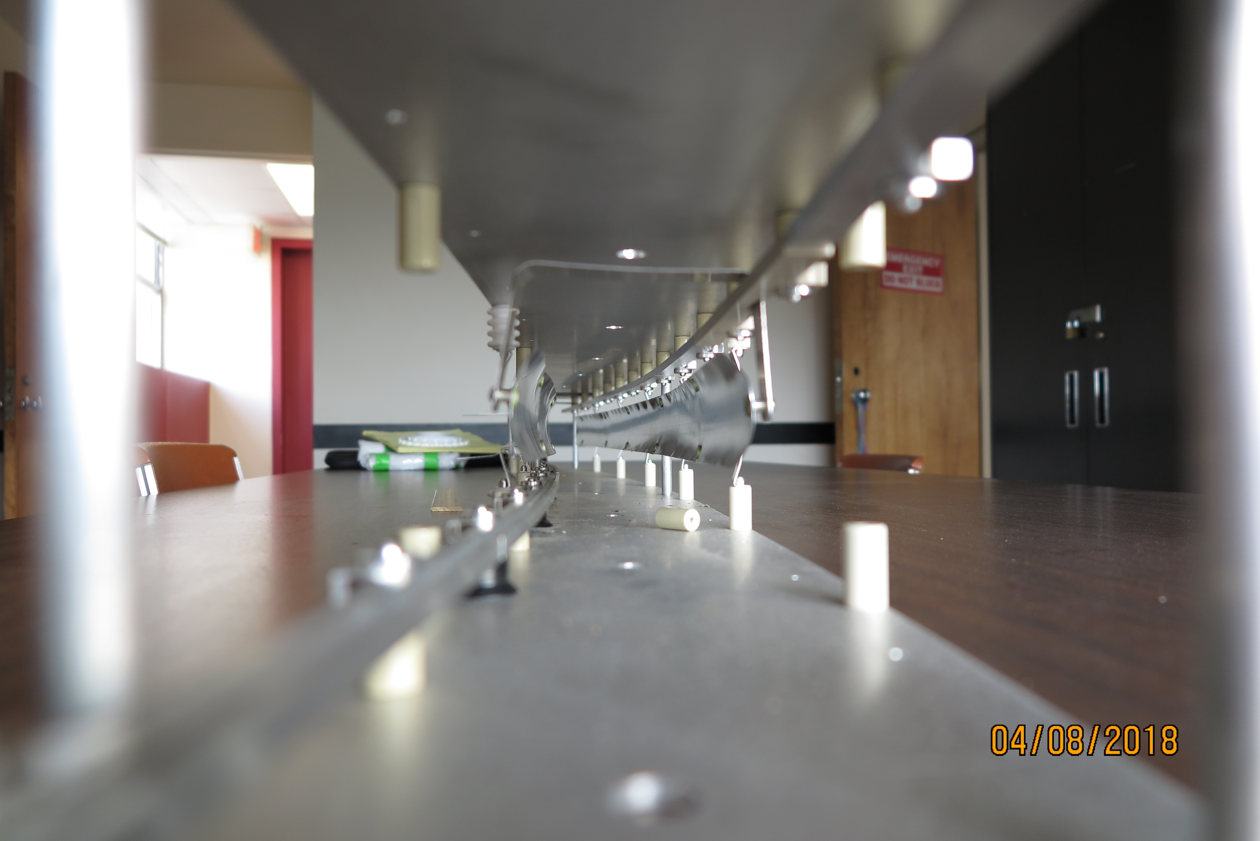
Another view of the kicker plates mounted in the cage.
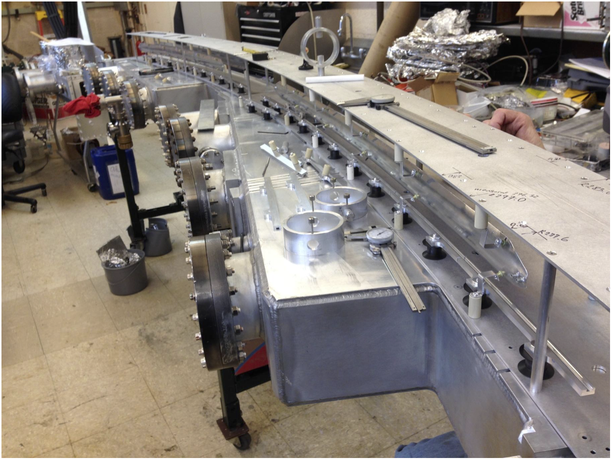
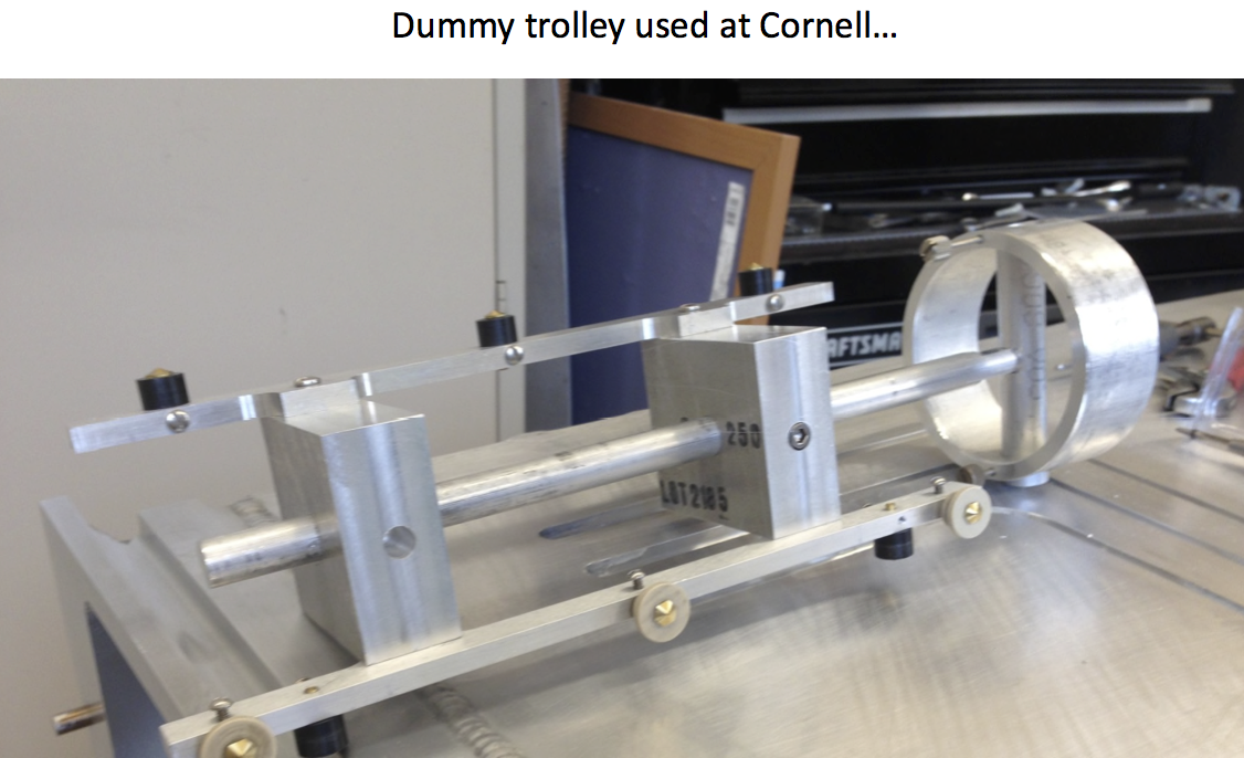
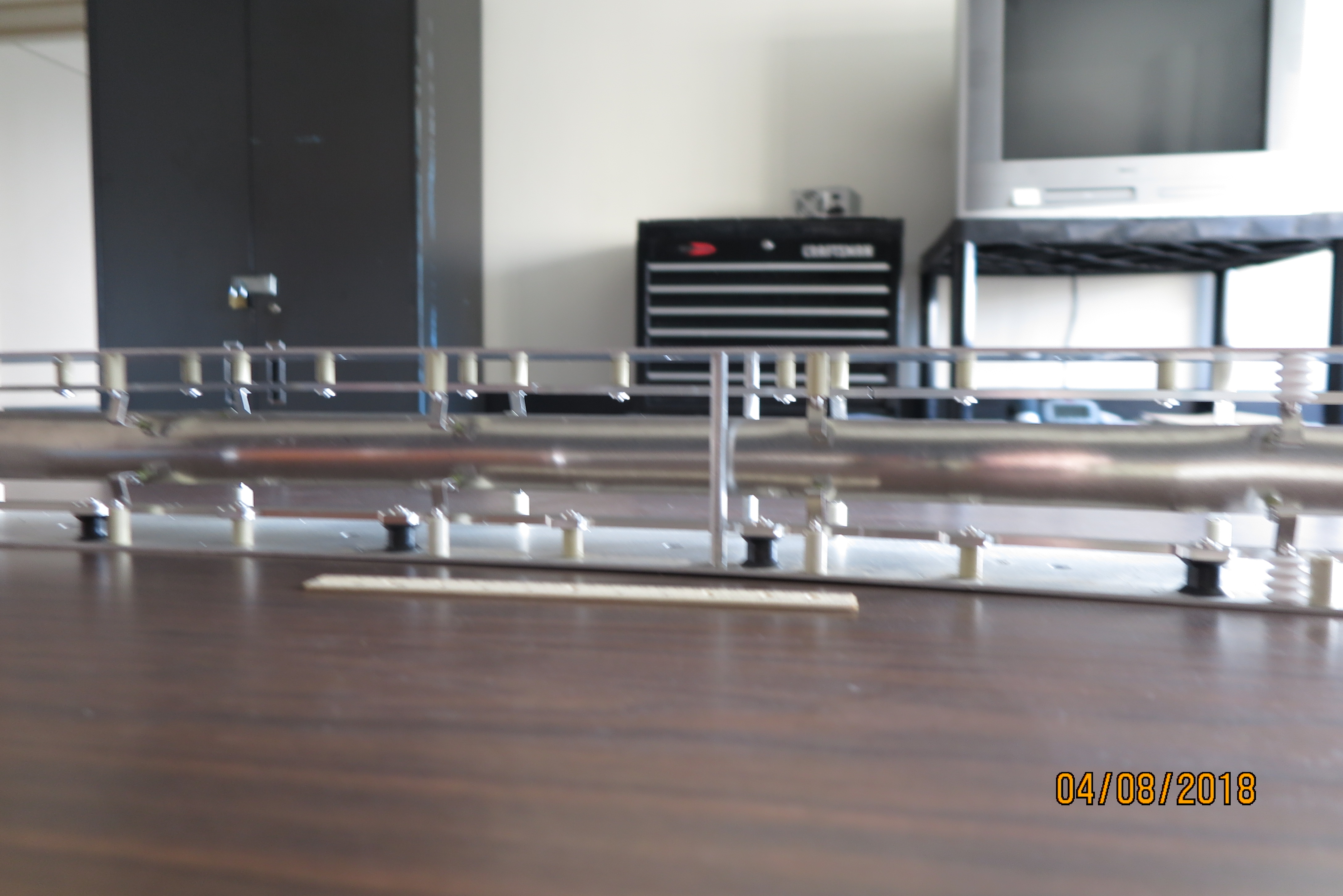
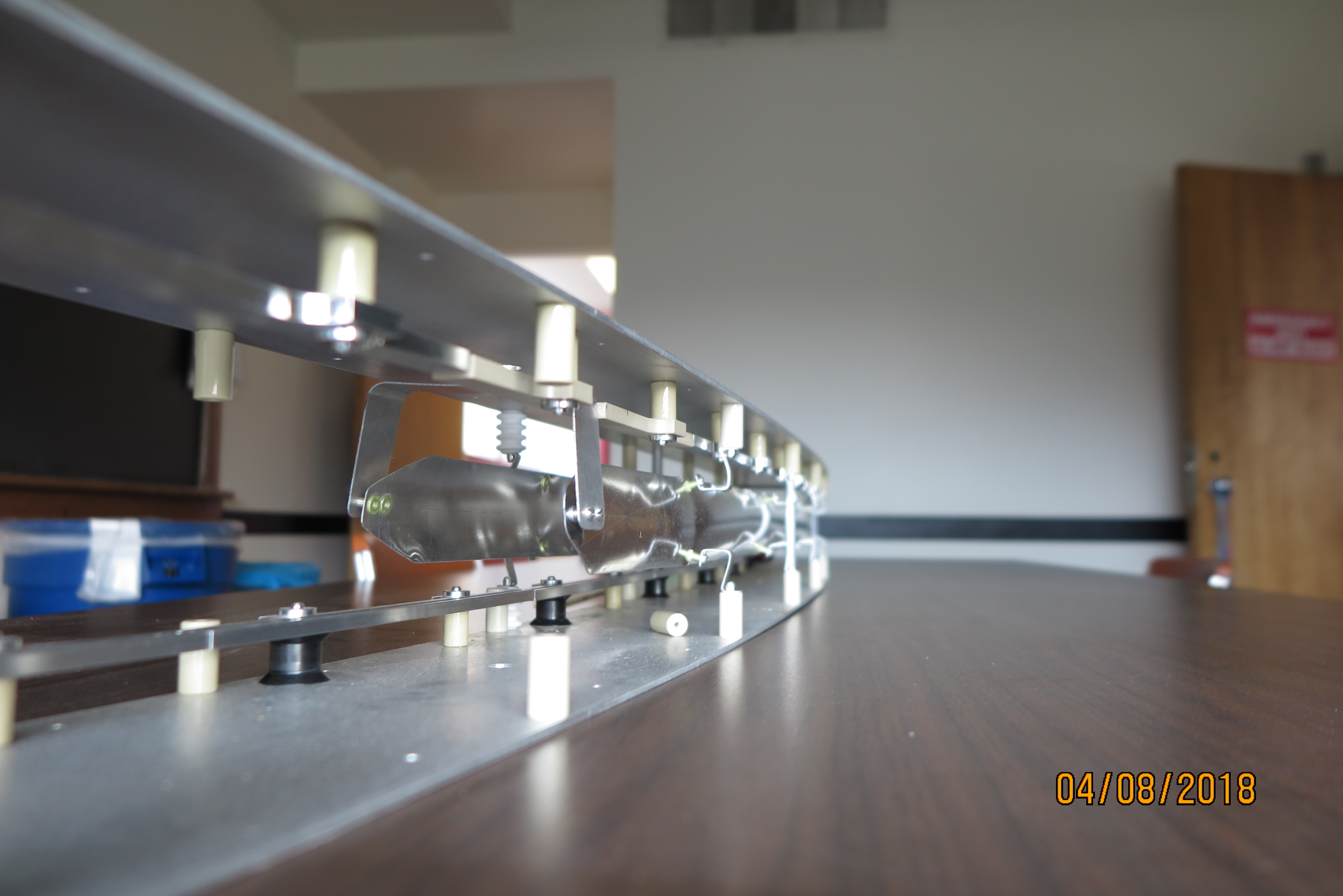
Two kicker magnets are assembled into their cage. The cage is resting on top of the vacuum chamber into which it will be inserted. The rings at the near
end are arranged to mimic the boundaries of the trolley to test clearance.
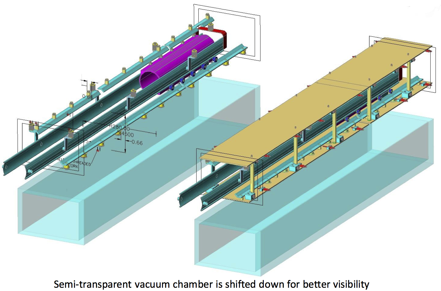
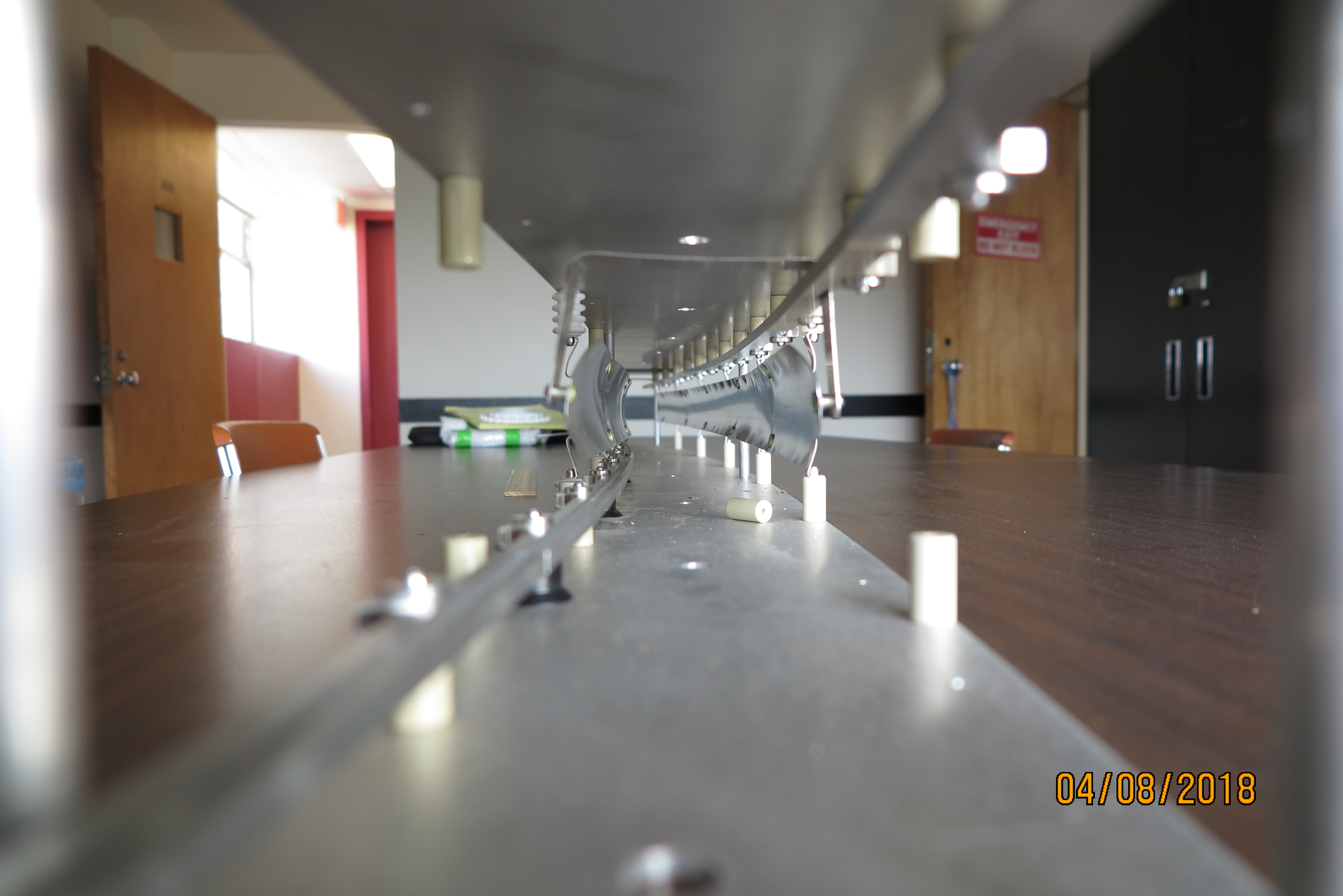
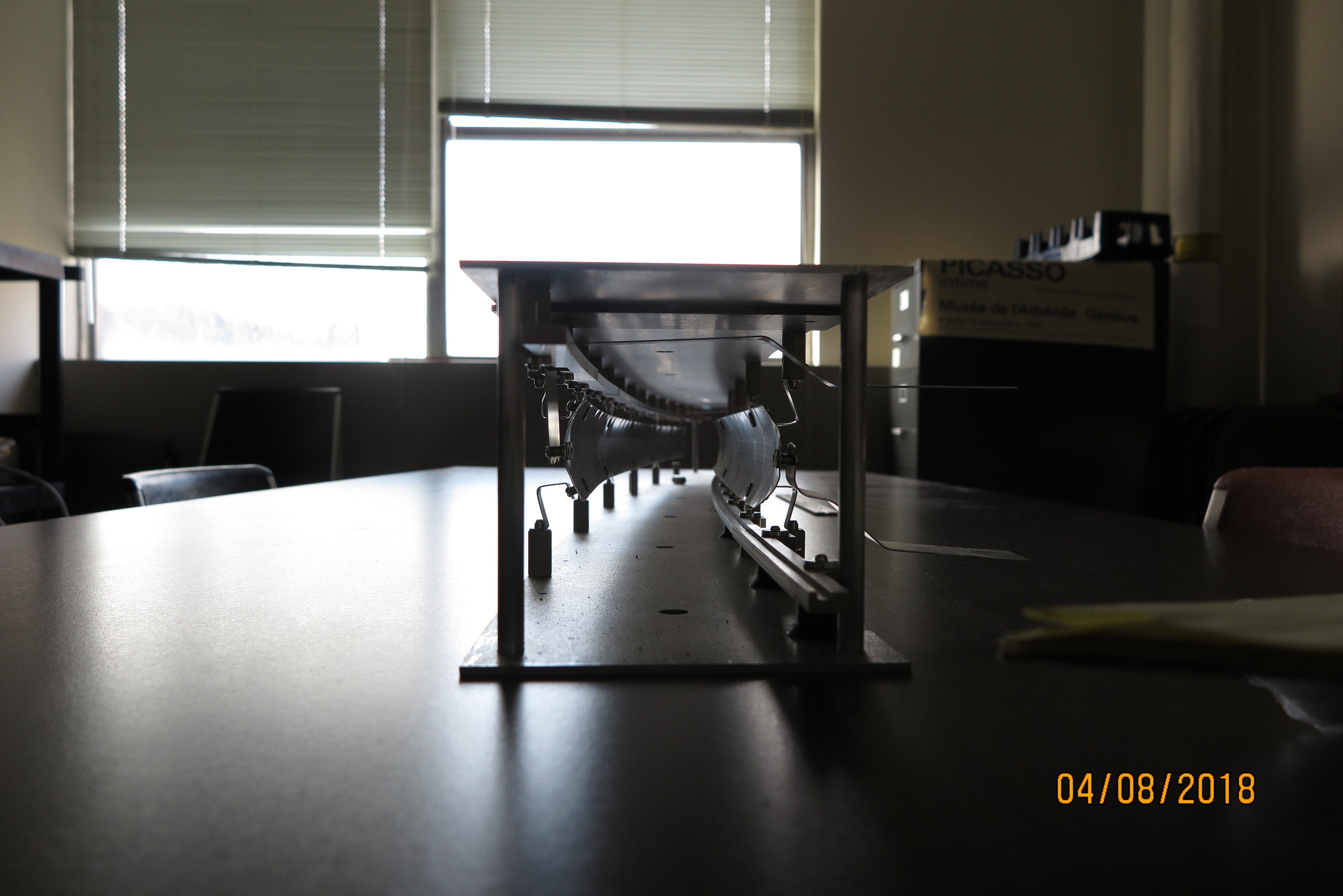
Another view of the double kicker assembly mounted in cages, and resting on the vacuum chamber in which it will be installed. The low and inside trolley rail is visible.
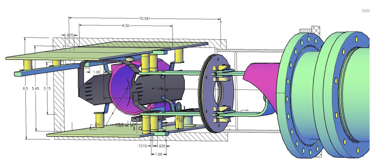
The drawing at right shows the upstream end of the kicker magnet mounted in the cage.
The outer plate is coupled to ground (outer plate of the transmission line) and the inner plate to the center conductor
of the transmission line via the high voltage ceramic feedthrough which is hidden behind the pink tube that extends out of the bazooka.
Geometry of E821 and E989 plates with respect to storage volume
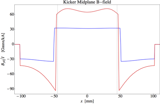
Magnetic field per unit current with E821 and E989 geometry
The calculated field profile along the vertical midplane for the E989 geometry is shown in the Figure at left and the measured field at right.
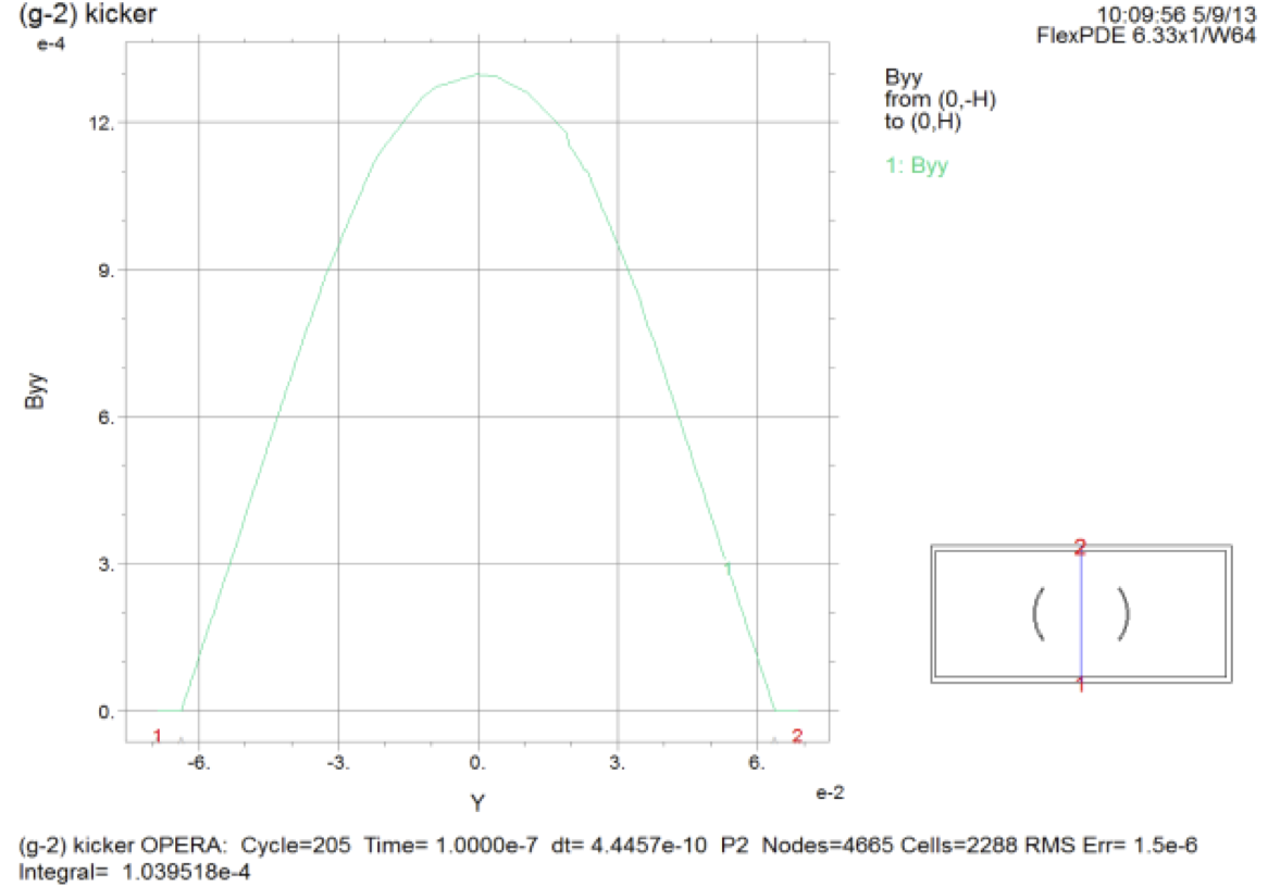
The field along the vertical midplane as computed with Opera.
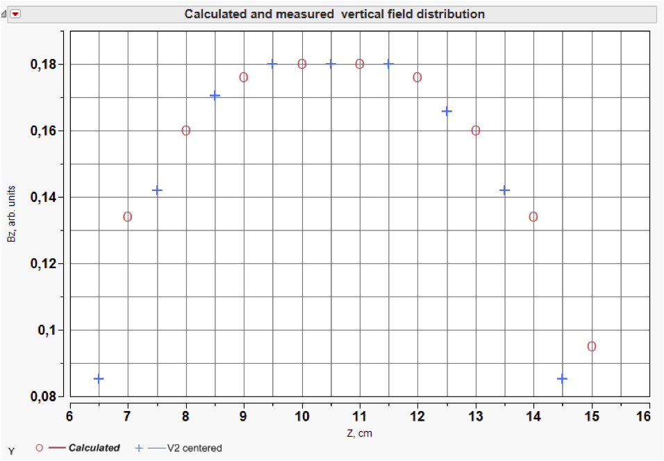
Calculated (o) and measured (+) vertical field distribution on vertical coordinate.
The margins at the center show the accuracy of measurements and positioning. Calculated distribution centered to the measured one and scaled (FlexPDE).
From the Figure it could be concluded that 10% variation of vertical field lies within z=±2.5 cm. Some discrepancy
at the side edges of this graph can be explained by large dimensions of coil.
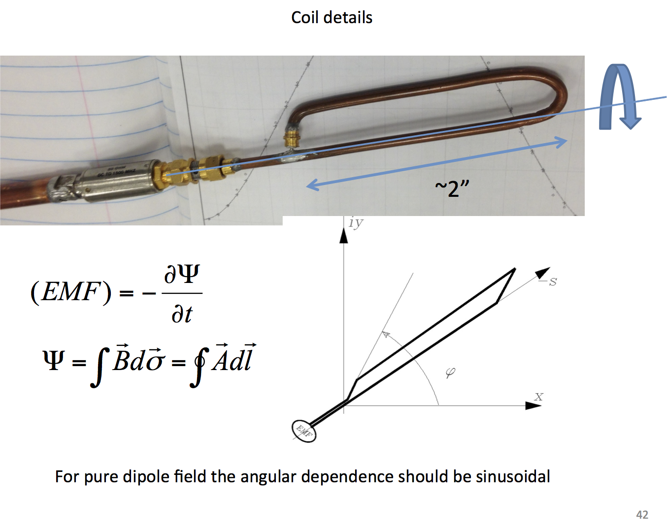
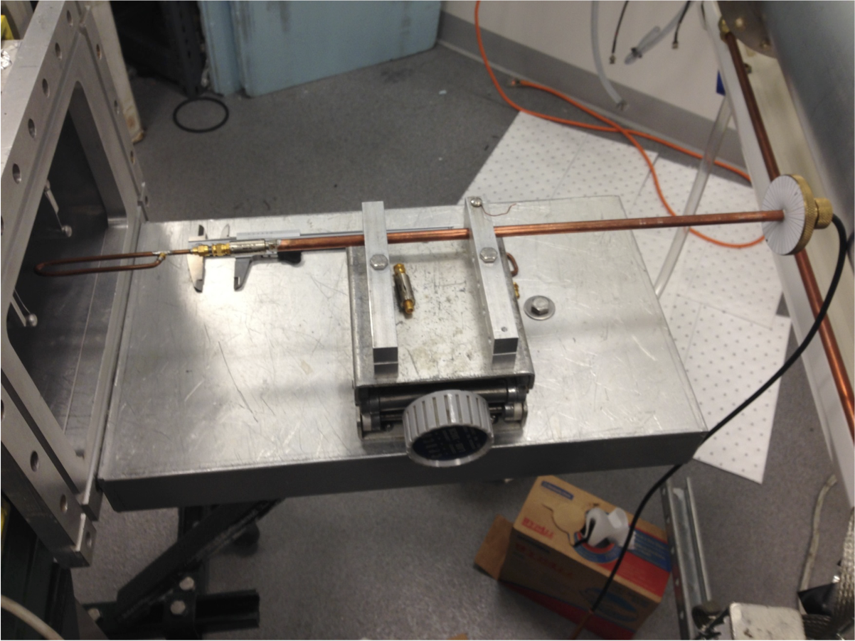
Instrumentation for measuring the kicker field includes a pickup coil and stage.
Field measuring coil
Measurement setup
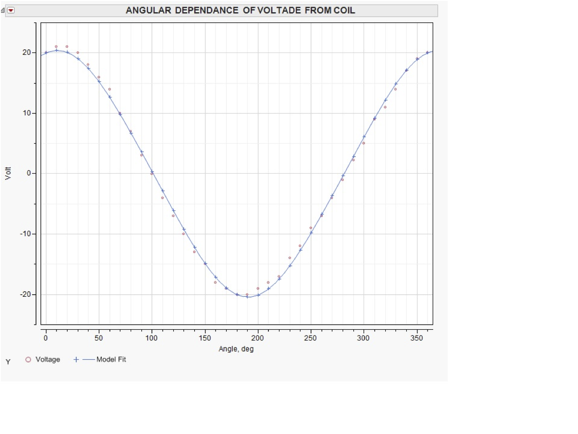
The azimuthal component of the field within 1/2 coil radius of the center, is measured by rotating the pickup coil about its axis. The sinusoidal dependence is consistent with expectation.
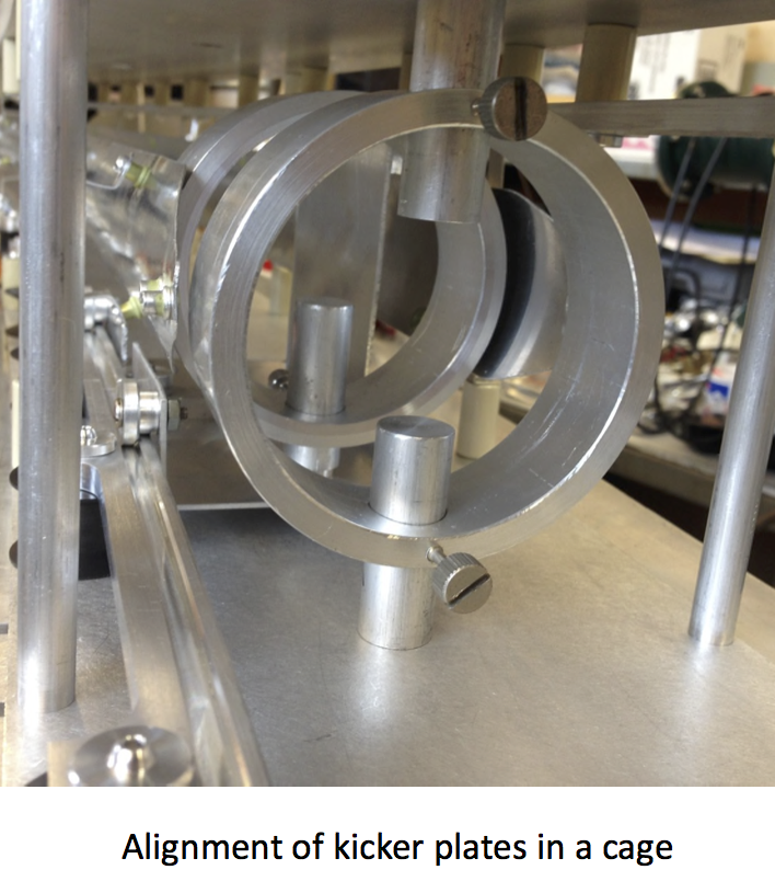
The rings are centered on the magic radius via the precision holes in the top and bottom plates of the cage.
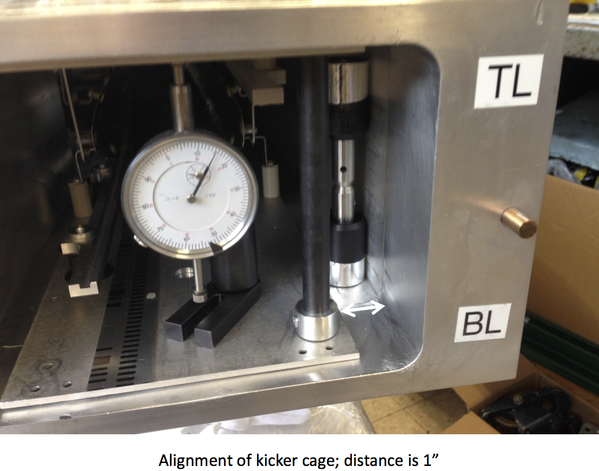
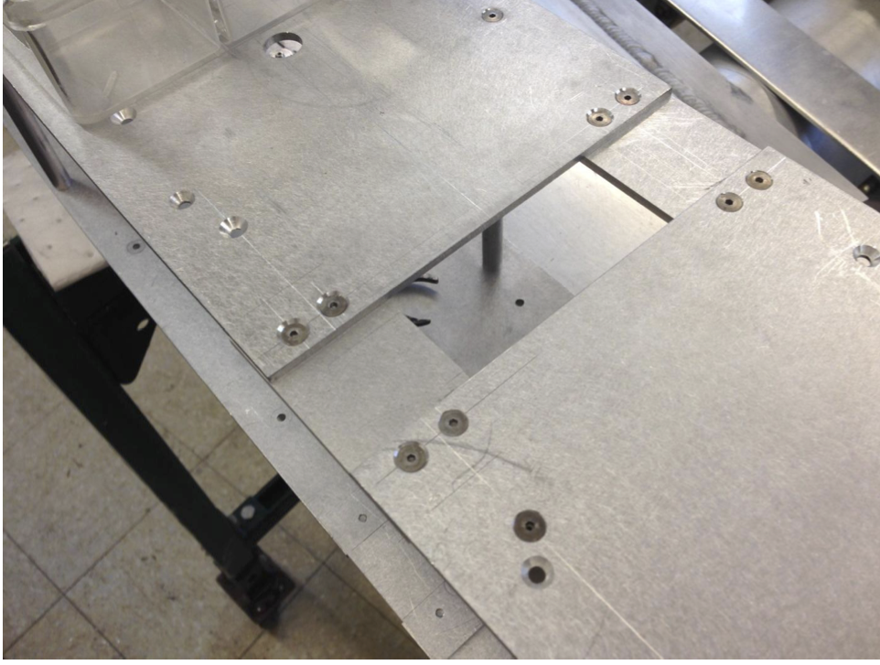
The photo at right shows the alignment of the cage with respect to fiducials on the vacuum chamber.
Alignment of the cage in the vacuum chamber. A hole on the top of the chamber (not visible here) locates the magic radius.
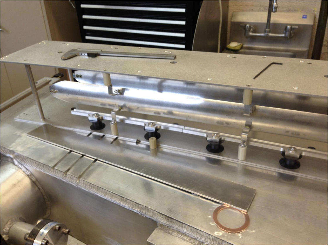
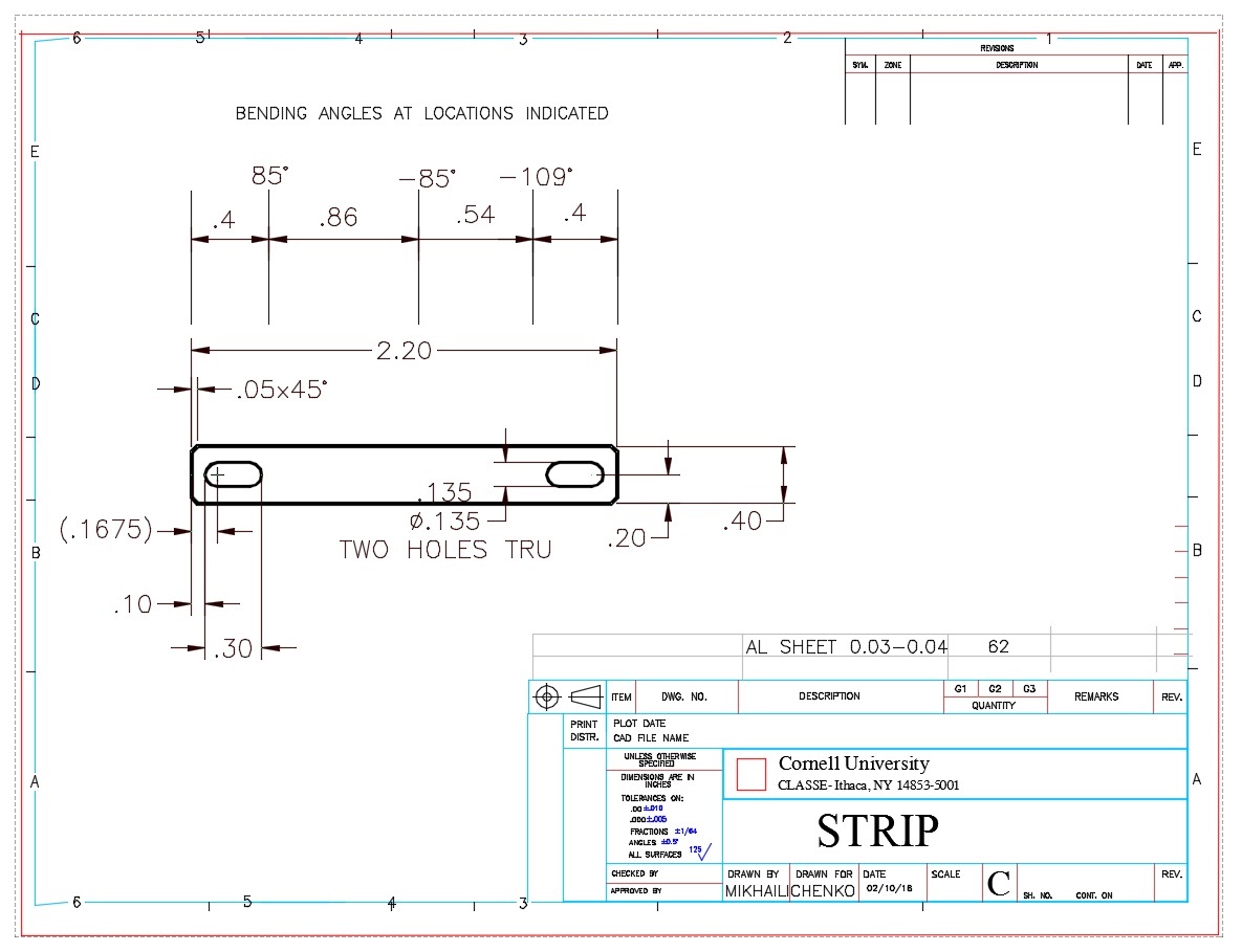
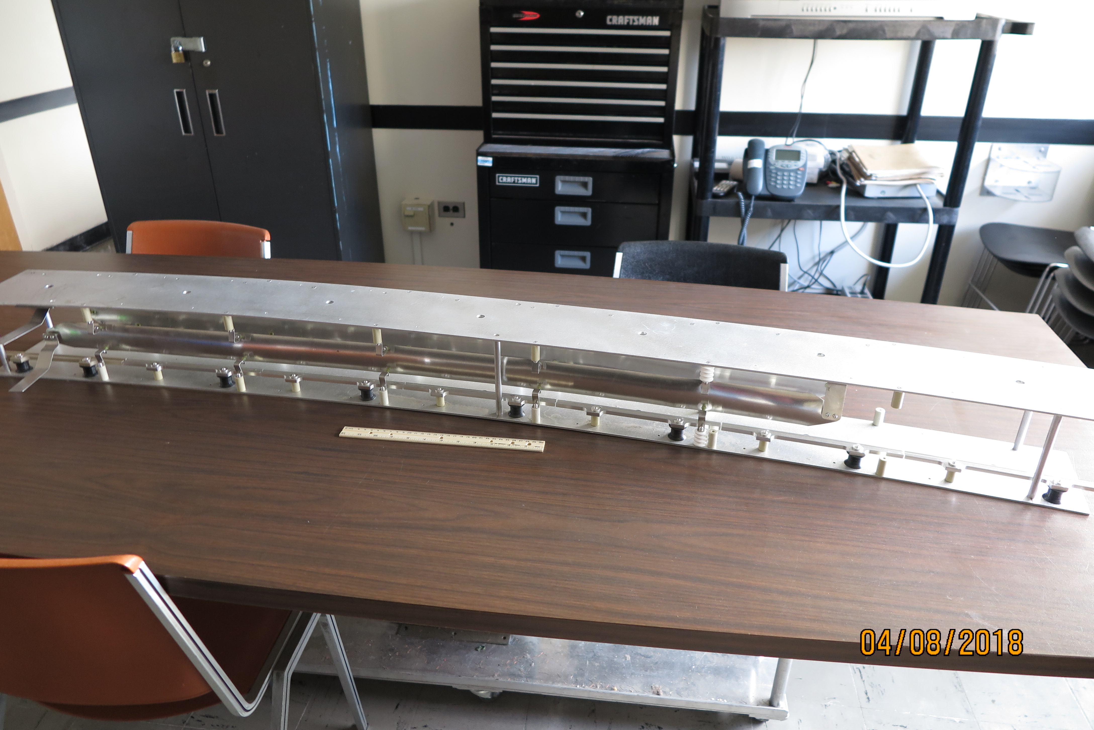
Kicker plates, support strips (see drawing above right) and ceramic standoffs.
Standoffs are Keystone 1/2 Round; Female, Threaded 6-32; L=1in, Grade L5 Ceramic Glaze, Part Number 7716