Mi double mirror, PhS photon shutter, D deflector, Diff diffractometer; source distances in m).
INDEX
ID10B is a multi-purpose diffraction beamline, with a special emphasis given to surface scattering geometries. Both the horizontal and the vertical scattering configuration can be exploited for scattering from liquid and solid surfaces, respectively. ID10B is equipped with a horizontal fixed-exit diamond (111) double crystal monochromator which is tunable in the energy range from 8 keV to 13 keV. A double mirror assembly, operated close to the critical angle, provides a suppression of the higher harmonics by better than a factor of 1e-4. The experimental hutch contains a beam deflector and a multi-purpose eight-circle diffractometer. A variety of detector arm options and detectors are available.
The experimental hutch is equipped with a deflector stage (D), mainly
for experiments on liquid surfaces. In order to follow the deflected beam,
the support of the diffractometer can be rotated around the deflector and
its height can be adjusted. The diffractometer (Diff) has a two-component
detector arm and a combined scattering stage for both horizontal and vertical
scattering geometries. The sample position on the diffractometer is at
41.7 m from the source.
|
|
|---|---|
| Fig. ID10B-1 | Schematic beamline layout (PS primary slits,
M1, M2 first and second monochromator vessel,
Mi double mirror, PhS photon shutter, D deflector, Diff diffractometer; source distances in m). |
The first monochromator crystal is a diamond (111) crystal of 120 µm thickness in Bragg geometry. The transmission of the first crystal is 65% for photons close to 9 keV. The crystal holder has two additional slots for a symmetric Laue and an asymmetric Laue crystal which can be translated into the white beam instead. Future candidates for monochromator crystals are Be(0001) and diamond (100).
Independent operation of ID10A and ID10B is guaranteed by two U42 undulators in the ID10 common front-end which can be operated simultaneously. Depending on the energy requirements, three modes of operation are possible:
The available energy range is given by the exit angle of the beryllium window (25° to 46°) of the first monochromator and the matching range of the translation stage of the second diamond(111) Bragg crystal. The second crystal is mounted on a high-resolution goniometer with the usual two rotations and two additional translations. The second monochromator vessel is operated under helium atmosphere, whereas the first monochromator in the white beam is operated in ultra-high vacuum.
 |
|
|---|---|
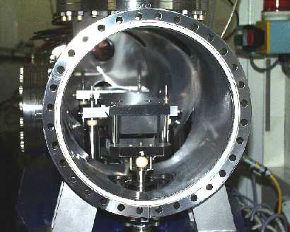
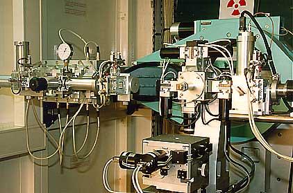
| Fig. ID10B-2 | ID10B main mirror looking upstream with the mirror vessel opened. |
The Troika II beamline is equipped with a compact double-mirror setup for a strong suppression of higher harmonics. This is particularly important for background reduction in liquid scattering experiments. The first mirror is a 300 mm silicon mirror with three strips (platinum, bare substrate, palladium) which adsorbs most of the higher harmonics passing the monochromator. The second mirror is a 300 mm Pyrex mirror with three corresponding strips. The mirrors are set typically to 80% of the critical angle of the respective strip material yielding a suppression of more than 10-4 of the intensity of third harmonic which is the most important high-energy contribution in the beam.
A ultra-high vacuum chamber houses both mirrors. Each mirror is actuated via bellows by three motorized high-precision jacks forming a kinematic mount. For controlling and aligning the mirrors the displacements of the jacks are converted into incident angle, sideways tilt, and height for both mirrors. The whole mirror assembly can be shifted sideways to choose the required strip material. At the end of the mirror chamber the beam position can be determined with a wire monitor.
In the standard geometry, the first mirror deflects the beam up and the second mirror reflects the beam back horizontally. Small downward deflections of the x-ray beam up to 2.5 mrad for liquid scattering experiments can be obtained by tilting the second mirror accordingly.
Another deflector option is the use of the Troika II horizontal multilayer bender. The elliptically-bent graded multilayer focuses the full width of the horizontal beam profile of about 1 mm into 25 mm (40:1 demagnification of the source), while the 0.3 mm height of the beam is conserved. The horizontal beam divergence will be on the order of 1 mrad in this case. This option is very useful for grazing-incidence diffraction experiments in the vertical scattering geometry that require very high flux at moderate resolution perpendicular to the sample surface. Furthermore the performance of the beamline in 16 bunch mode and even in single bunch mode gets strongly enhanced and the reduced available intensity in these special operation modes can be compensated for.
In order to follow the deflected beam, the diffractometer is supported
by a table which can be moved on airpads around the deflector axis from
0° to 30°. The table height can be adjusted from -130 mm to +70
mm, accordingly. The incident beam flight path comprises an aluminium attenuator
wheel, a second optional mirror, a set of motorized secondary slits defining
the beam profile at the sample, and a Kapton x-ray monitor. Other optional
devices are a filter inserter box and motorized guard slits or collimating
slits.
 |
|
|---|---|
| Fig. ID10B-3 | Schematic side view of the Troïka II instrumentation in the experimental hutch.. |
 |
|
|---|---|
| Fig. ID10B-4 | ID10B diffractometer - axis names in sixc and id10b configurations. The main slits are also shown. . |
The sample stages were designed to maximize the available volume for
sample environments. The horizontal sample stage consists of a horizontal
turn table, a height translation and crossed arcs. In combination with
the deflector this stage has a six-circle or z-axis configuration. The
horizontal stage is primarily used for scattering from liquid interfaces.
Furthermore heavy sample environments up to 100 kg can be supported without
counterweighting. A hemispherical volume of 450 mm diameter is available
for sample environments. The sample position is 170 mm from the top of
the crossed arcs. Optionally a xy-translation stage can be added on top
of the arcs. The horizontal sample stage has been used to support the beamline
Langmuir trough developed in collaboration with the Saclay-Group or a portable
UHV chamber.
 |
|
|---|---|
| Fig. ID10B-5 | Sample stages of the ID10B diffractometer. View in beam direction facing downstream. |
The vertical sample stage comprises a vertical turntable and a long z translation which permits to position the sample surface precisely into the beam, or otherwise remove this stage from the scattering position, if necessary. This stage is controlled by a 2+2 diffractometer code (two detector axes and two sample axes). Additionally the sample goniometer has crossed arcs to line up the surface normal parallel to the vertical scattering rotation axes. x and y translations permit to choose a good spot on the sample. The sample position is at 110 mm from the top plate of the crossed arcs. The vertical scattering stage can be used for small sample environments of less than 2 kg and 250 mm diameter, i.e. helium-filled cells or electrochemical cells.
 |
|
|---|---|
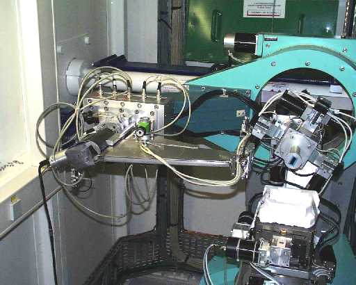
| Fig. ID10B-6 | ID10B 8-circle diffractometer with horizontal and vertical sample stages and standard detector arm. |
The detector arm has three possible configurations: The default configuration
comprises an MicroControle X48 optical bench, motorized front slits, variable
length flight path with Kapton windows and motorized detector slits. Either
a scintillation detector, a Kapton detector or a 50 mm linear detector
(MBraun) can be used with this set-up. Alternatively the X48 bench can
be equipped with a 150 mm Soller collimator of 1.4 mrad resolution and
a 150 mm linear gas detector (Gabriel, EMBL) for the horizontal scattering
configuration.
 |
|
|---|---|
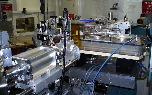
| Fig. ID10B-7 | ID10B analyzer stage and flightpath mounted in the vertical scattering geometry.. |
The second configuration consists of an analyzer stage. In horizontal scattering geometry a 150 mm Si(111) analyzer crystal can be combined with a 150 mm linear gas detector. In vertical scattering geometry various 50 mm analyzer crystals (Si(111), Ge(111)) can be combined with a 50 mm linear gas detector.
The third configuration of the detector arm provides a mount for a MicroControle X95 profile which can be used for equipment that was originally designed for the Troïka I station.
Sample Environment: Langmuir
Trough
 |
|
|---|---|
| Fig. ID10B-8 | Beamline Langmuir trough view downstream from the incoming flightpath.. |
In collaboration with Alan Braslau, Jean Daillant, and Daniel Luzet
from CEA Saclay a Langmuir trough for the Troika II beamline was built.
The trough is a copy of the Saclay Trough, slightly modified to fit better
on to the ID10B diffractometer.
The width of the Teflon-coated trough is 150 mm with a length of about
500mm. A ribbon barrier is used to compress monolayers on the water surface.
Scattering angles of up to 50° can be reached. The trough is seated
on a Halcyonics active vibration damping system. The surface pressure can
be monitored with Wilhelmy balance and is controlled by the analog feedback
system by Riegler and Kirstein. Using analog-to-digital and digital-to-analog
converters, the feedback electronics can be interfaced with the SPEC beamline
control program.
Basic data evaluation can be performed on a second terminal of the work station or on the beamline PC. Data from the workstation can be directly accessed from the PC. Some basic software for data analysis and commercial software packages are available on the workstation and on the PC.
Data Analysis Software Development
 |
|
|---|---|
| Fig. ID10B-9 | The six degrees of freedom of a rigid molecule on a surface. |
For the structure determination of molecular layers on well-defined solid surfaces, I initialized the ANA/ROD project in collaboration with Olof Svensson, Rainer Wilcke, and Claudio Ferrero of the Scientific Software Group at ESRF. Goal was to extend the ROD surface structure analysis program by Elias Vlieg, to be able to handle molecules. The basic idea was to treat a molecule as an entity which can be rotated around the Eulerian angles and translated in three directions within the unit cell, in order to reduce the degrees of freedom for initial modelling. The resulting "Svensson's extension" of ROD is available on the web.
A Brief ID10B Beamline History
ID10B exploits mostly ESRF in-house designs:
| diamond beamsplitter | Gerhard Grübel and Andreas Freund |
| UHV monochromator | Gerhard Grübel and Muriel Mattenet |
| fixed exit monochromator | Gerhard Grübel, Detlef Smilgies, and Keith Martel |
| deflector | Detlef Smilgies and Keith Martel |
| diffractometer | Detlef Smilgies and HUBER Diffraktionstechnik |
| main mirrors | Detlef Smilgies and Muriel Mattenet |
| analyzer stage | Detlef Smilgies, Nathalie Boudet, and Muriel Mattenet |
| multilayer bender | ESRF Optics Group |
| beamline Langmuir trough | in collaboration with Alan Braslau, Jean Daillant, and Daniel Luzet (CEA Saclay) |
The diamond (111) beam splitter crystal was provided by Friedel Sellschop (University of Witwatersrand, South Africa) and Andreas Freud (ESRF) from a large synthetic diamond grown by deBeer, South Africa. The second (111) diamond, also synthetic, was provided by Sumitomo Electric, Japan. The main mirrors were manufactured by Optique Fichou, France. High quality deflector and analyzer crystals as well as the graded multilayer were provided by the ESRF Optics Group (Andreas Freund, André Paul, Olivier Hignette, Christian Morawe). Assembly and wiring of the beamline components was done expertly within the Troika Group by Patrick Feder and Henri Gleyzolle with support from ESRF Technical Services, the ESRF Engineering Office (Muriel Mattenet, Keith Martel, Gilles Retout) and the ESRF Computer Group (Jörg Klora).
Troïka II started User Mode in April 1998. Scientific beamline
staff of the first years consisted of myself (3/1996-5/2000), Nathalie
Boudet (11/1997-12/1998), Bernd Struth (7/1998 to present) and Oleg Konovalov
(3/1999 to present). The installation and commissioning of the main mirrors
in summer 1999 marked the end of the basic beamline construction.
An account of the scientific work performed at ID10B was presented in various
contributions to the ESRF User Meeting satellite workshop "Surface
Science 2000: Self-Organization at Interfaces and in Thin Films".
Appendix: Troïka
II Overview in Numbers
| scientific applications | Open undulator beamline for grazing-incidence scattering and reflectivity | ||||
| source parameters | high b straight section | ||||
| 2 x U42 undulators | small gap undulator | ||||
| undulator period lu | 42 mm | 26 mm | |||
| Kmax | 2.2 | 1.7 | |||
| field Bmax | 0.565 T | 0.71 T | |||
| source size | 928 x 23 µm2 (HxV) FWHM | ||||
| source divergence | 28 x 17 µrad2 (HxV) FWHM @ 10keV | ||||
| peak brilliance | > 1019 ph s-1mrad-2mm-2 (0.1% bw, 100 mA @ 8 keV) | ||||
| power | 1.05 kW (single U42) | ||||
| power density | 32 W mm-2 (single U42) @ 30 m | ||||
| optics | primary slits | monochromator | mirrors | ||
| distance from source: | 27 m | 30.5 m | 41 m | ||
| focusing: | none at present | ||||
| beam size at sample: | < 1 x 0.5 mm2 (HxV) | ||||
| intrinsic resolution DE/E: | 6 x 10⁻⁵ diamond (111) | ||||
| flux at sample: | 1011 ph/s (100 mA @ 8 keV) | ||||
| detectors | Scintillation detector (Cyberstar) | Ø 10 or 25 mm | |||
| Kapton detector (Kapton scatterer + Cyberstar) | Ø 10 mm | ||||
| 50 mm gas detector (MBraun) | 50 x 10 mm2 | ||||
| 150mm gas detector (Gabriel/EMBL) | 150 x 10 mm2 | ||||
| analyzer crystals | Si(111) | 170 x 40 mm2 | only in horizontal scattering geometry | ||
| Ge(111) | 170 x 40 mm2 | symmetric cut | |||
| Si(111) | 60 x 40 mm2 | symmetric cut | |||
| Si(111) | 60 x 40 mm2 | asymmetric cut, b=10 at 9 keV | |||
| Si(111) | 60 x 40 mm2 | asymmetric cut, b=0.1 at 9 keV | |||
| beamline control | HP 715/80 workstation, SPEC control software | ||||
| ancillary equipment | beam deflector using Si(111) and Ge(111) Bragg crystals or Pt coated Pyrex mirrors, horizontal focussing multilayer bender, analyser, Soller collimators, Langmuir trough | ||||
In spring 2000 I accepted an offer from Cornell University as staff scientist for the G-line project. Oleg Konovalov succeeded me as responsible beamline scientist for ID10B in May 2000. For the most recent detailed description of the Troika II beamline see the ID10B home page.
Detlef Smilgies, August 2001back to Detlef's home page