This page contains the the Gas Seal tests
2008-07-16 O-rings
Viton o-ring material was purchased and tested.
Gas seal test is still good. (By the way, the gas seal test, started in August 2007, had shown no loss since December.)
Torque to compress o-ring (see Gas Seal page, 2007-11-22) increased from 11 inch-pounds to 12 or 13 inch-pounds. This creates an increase of ~20% in the force on the field cage inserts and should be OK with the safety factor that was built in.
2007-11-22 Torque to compress the o-ring
I measured the torque required to compress an o-ring and the yield torque for
brass screws.
The o-ring is 3.55mm in a groove with 3.65mm width and 2.75mm depth. This is my standard 4-surface contact, high compression, groove.
The original measurements, 2007-11-19, were sloppy.
I used the full length o-ring and counted on the bending of the cover plate to select only a section of the length.
I have repeated the measurements using a 6cm length of o-ring material centered on one screw.
This is the distance between screws in the outer flange.
I also now explicitly discuss a safety factor.
-
For 5mm x 0.8mm screws, the compression torque is 8 inch-pounds while the yield torque is 55 inch-pounds.
Compression is achieved at 0.15xYield.
-
For 6mm x 1.0mm screws, the compression torque is 11 inch-pounds while the yield torque is 130 inch-pounds.
Compression is achieved at 0.08xYield.
As described below, much of this improvement could be due to a difference in screw alloy.
-
Compression torque should be proportional to screw diameter (which diameter?) ...
11/8=1.38, not 1.2 .
So, there is some inconsistancy in the measured compression torques.
-
The compression force,
the force which must be held by each insert in the field cage flange, is somewhere between 236-272lbs (1050-1210N).
This is the the force that must be held on each screw after all the screws are placed and the load is uniformly distributed.
The safety factor for the pull-out force of the inserts should be at least 3 to account for nonuniformities that can arise while tightening the screws.
The inserts should be tested at 3600N.
-
Yield torque (if the yield mode is axial stretch) should be proportional to diameter**3 (again, which diameter?) ...
130/55=2.36, not 1.738.
However, the 5mm and 6mm screws that I tested were from different country-of-origin and could be different alloys.
Fortunately, it appears that even the weaker screws had tensile strength above the rated minimum.
-
Because the endplate is rigid, simply tightening one screw connecting the endplate to the field cage would result in a force beyond the screw yield or the insert pull-out force.
Installation of the screws will require a sequence and the use of a torque wrench to avoid damage.
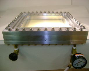
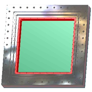
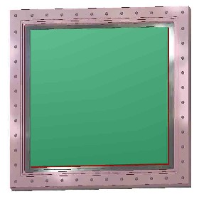
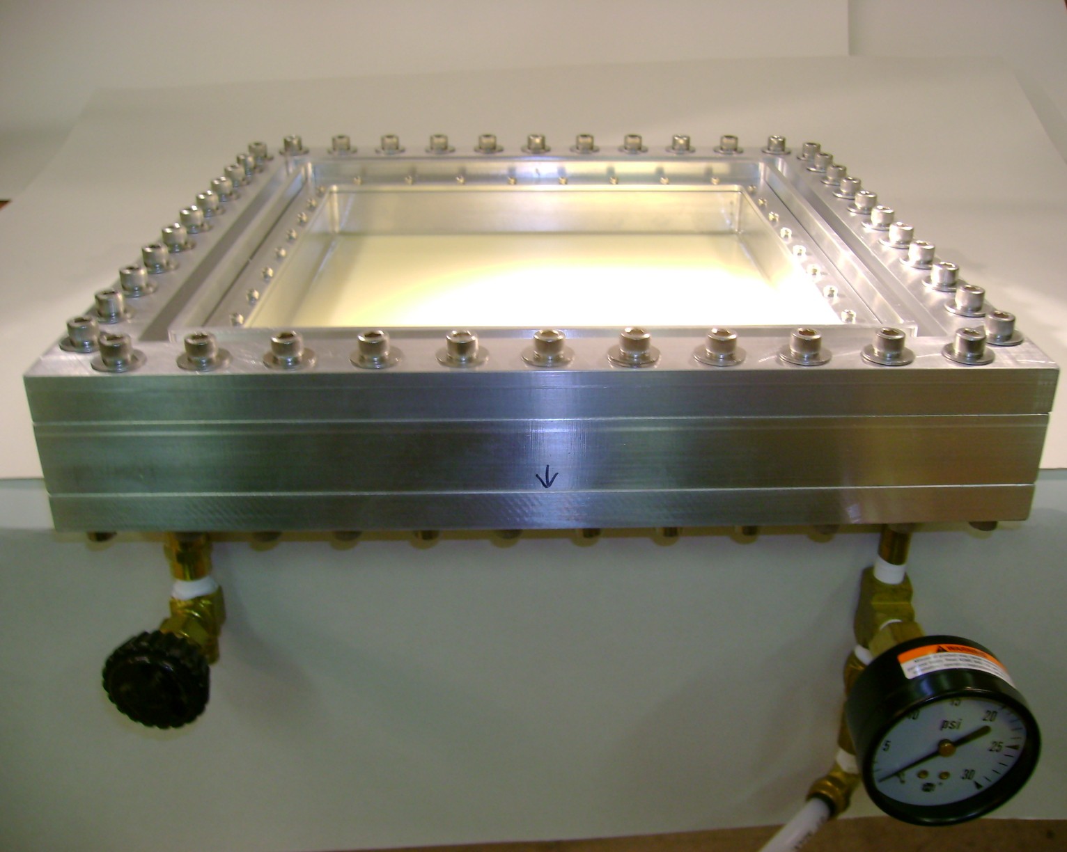
2007-08-21 Gas seal test
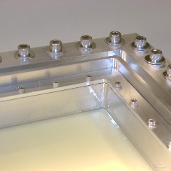
The gas seal test has has been completed with
the captured gas on the
pad-board
side of the module
while the "outside of the chamber" is exposed to air,
as shown in the first two figures.
-
The o-ring groove for the large o-ring, which seals the test chamber, was reduced in depth to increase the o-ring compression.
At the same time, the o-ring splice (where the circle is closed) was polished.
-
A flat plate was installed in place of the "endplate" and "module",
-
After these improvements,
there were no background leaks.
After 64 hours, the pressure changed from 30.1 inches-of-water (~60 millibar) to 32.0 inches-of-water.
(The increase can be attributed to atmospheric fluctuations.)
-
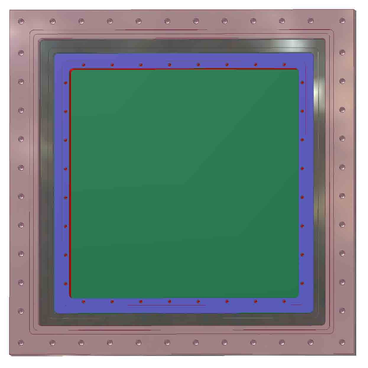
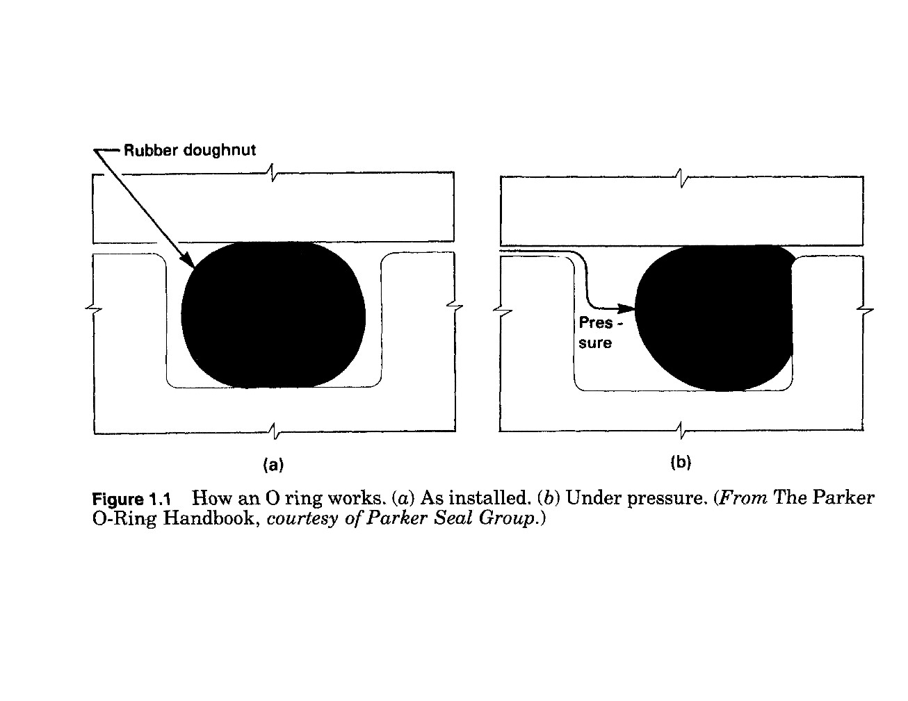
I use a 3.55mm (0.139inch specified, 0.135inch actual measure)diameter o-ring with a 4-surface contact groove and large compression. There is, of course, no lubricant.
The groove has dimensions: 3.56mm (0.140inch) in width and 2.74mm (0.108inch) in depth.
Thus, when compressed, the o-ring fills 95% of the groove (if cross section is conserved, which it is not).
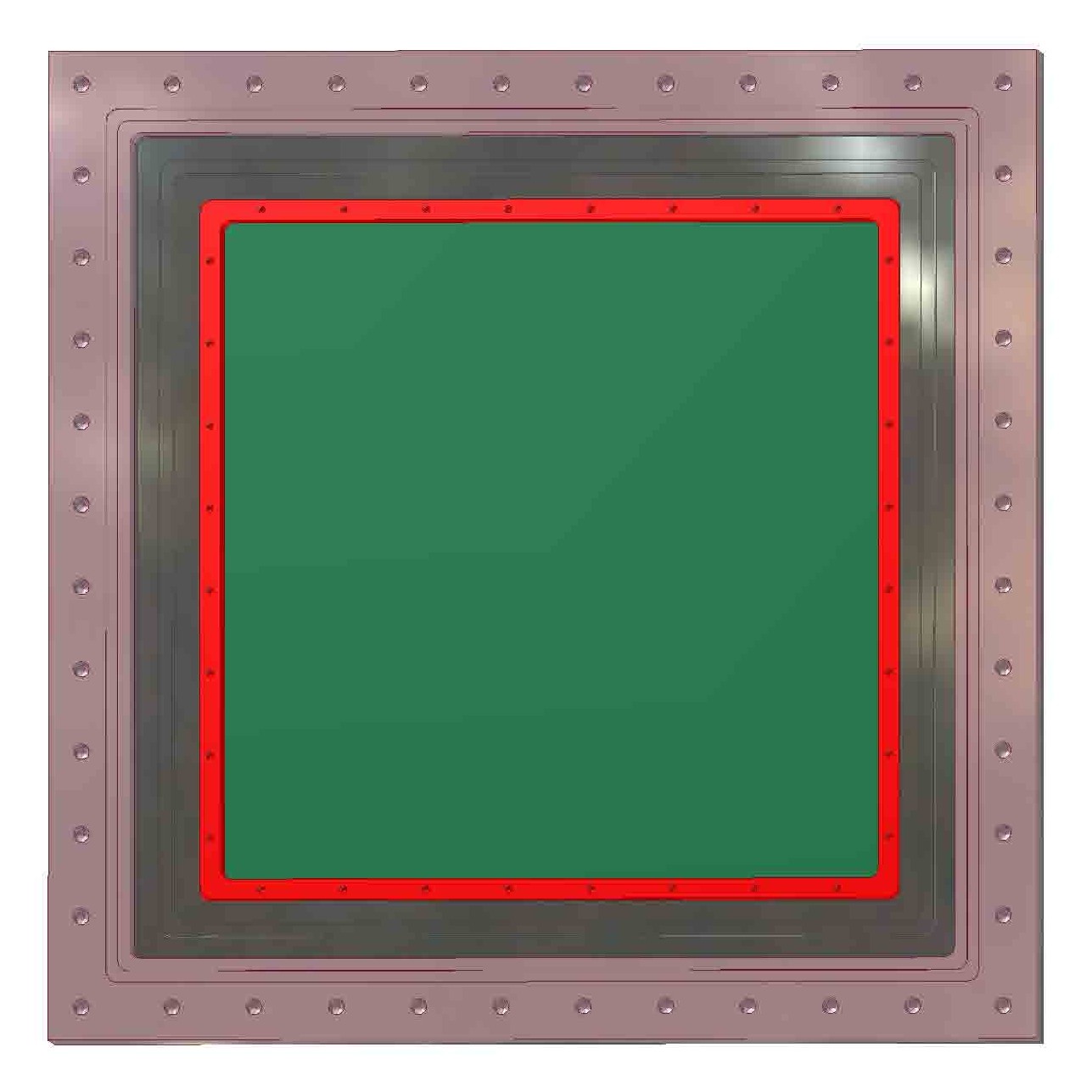
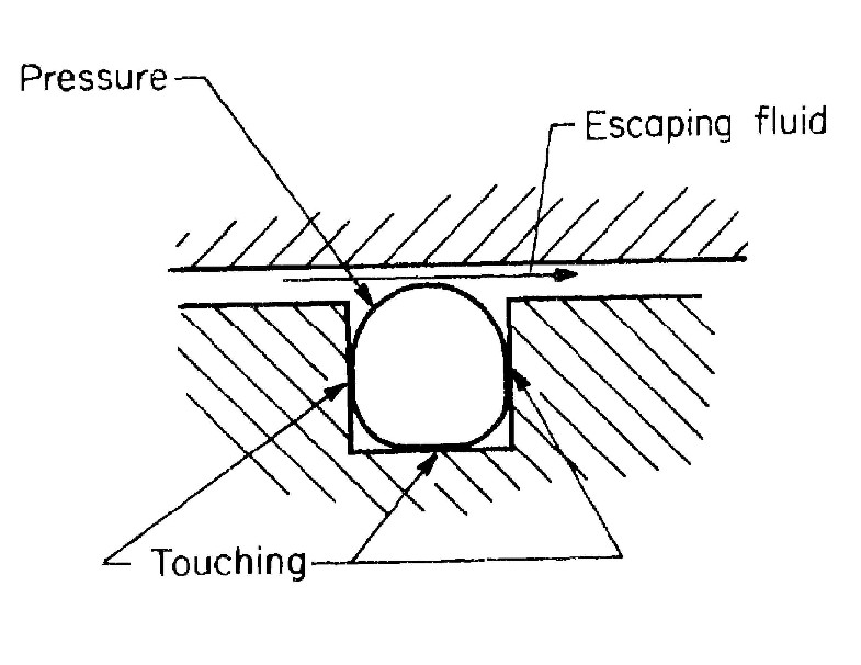
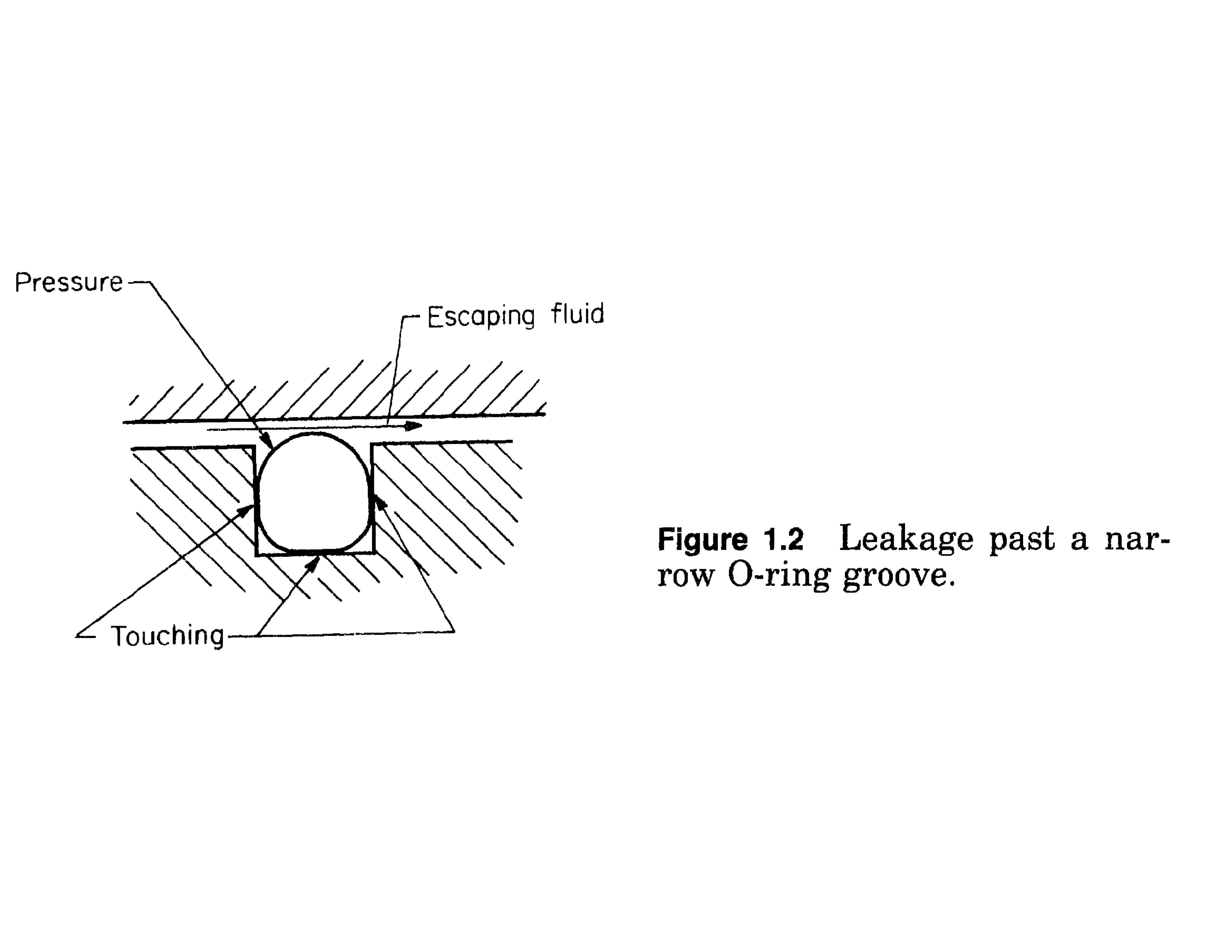
This is in contrast to the standard practice for a 2-surface contact, as shown in the third figure.
Here, the groove has dimensions: 4.83mm (0.190inch) in width amd 3.07mm (0.121inch) in depth. (Dimensions are from the US manufacturer, Parker.) This is a high pressure application.
The captured pressure is used to push the o-ring into the joint, as shown in the third figure.
We will not have this high pressure to to complete the seal.
Although the 4-point contact, as shown in the 4th figure, would fail in a high pressure situation, I believe it is better for this application.
I then installed the "endplate" and "module" as shown in the first two figures.
-
After 168 hours,
the pressure changed from 20.1 inches-of-water (~40 millibar) to 13.0 inches-of-water. "Fitting" to an exponential, P=P0*exp(-t/a), the charateristic time is, a=385 hours.
-
The leak rate for a partial pressure of oxygen, 180millibar, is then 180/385millibar/hour, or .00047 bar/hour
-
As described 2007-05-08, the captured volume is ~275cc, so the
volume leak rate of oxygen would be 0.13cc/hour per module.
This is a factor of 30 improvement from the earlier result.
Most of the leak reported 2007-05-08 can be attributed to the test chamber seal.
-
I use a 1.78mm (0.070inch specified, 0.072inch actual measure)diameter o-ring with a 4-surface contact groove and large compression.
There is, of course, no lubricant.
The groove has dimensions: 1.91mm (0.075inch) in width and 1.45mm (0.057inch) in depth.
The corners have 3.18mm (0.125inch) radius on the smaller perimeter wall and constant width through the corner.
When compressed, the o-ring fills 95% of the groove (if cross section is conserved, which it is not).
 (pdf)
(pdf)
 (pdf)
(pdf)
2007-05-08 Gas seal test
The gas seal test has started with
the captured gas on the
pad-board side of the module
while the "outside of the chamber" is exposed to air.
Corrections should be made to the 0-ring slots:
the outer radius at the corners was maintained at the same value as the inner radius, rather than increasing the radius by the width of the o-ring.
The 0.071inch o-ring is fitted in a 0.075inch slot, 0.057inch deep. Therefore the compression is 0.014inch.
(The compression to fill the cross section of the slot would be 0.018 inch.)
Initial observation: The volume, ~275cc, was overpressured with air to 1.06 atmosphere absolute (1psi gauge).
After 1.3 hours, the pressure had dropped by 0.006 atmosphere.
Thus, the leak rate, at the applied overpressure, is (0.006*275cc)/(1.3hour) =~1.3cc/hour.
Of course, the leak-rate-in of oxygen will depend on the partial pressure of oxygen, which is 3x the overpressure that was used in this test. So, this leak rate could be ~4cc/hour per module.
This is probably not acceptable.
This is an upper limit of the leak rate through the module seal; there are many other potential locations.
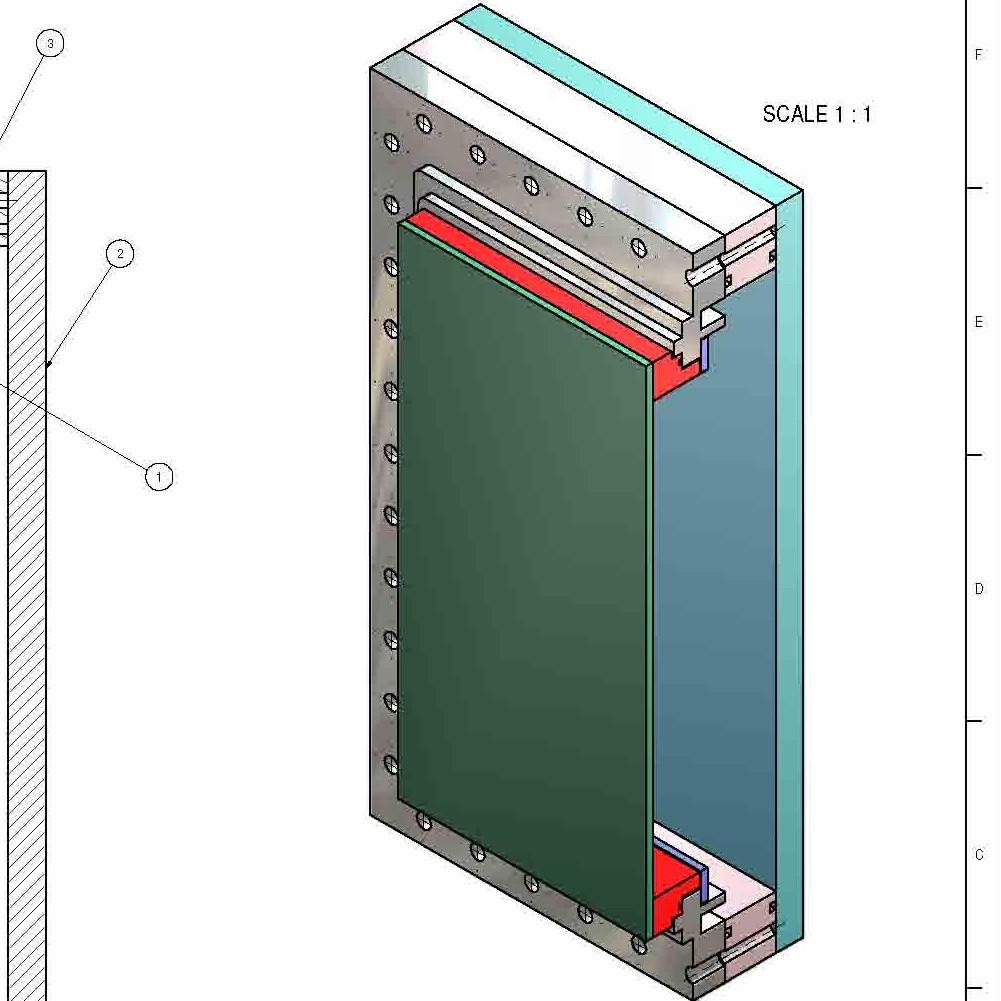
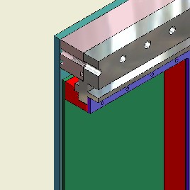
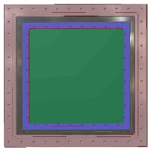
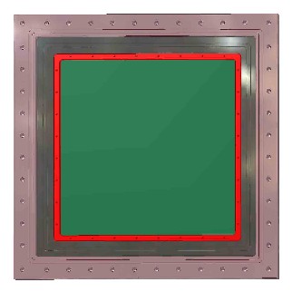
2007-04-10 Gas seal test
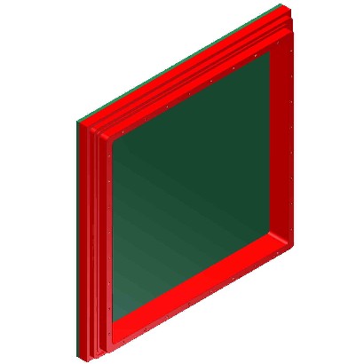
We will perform a series of tests of the gas seal design of the readout module.
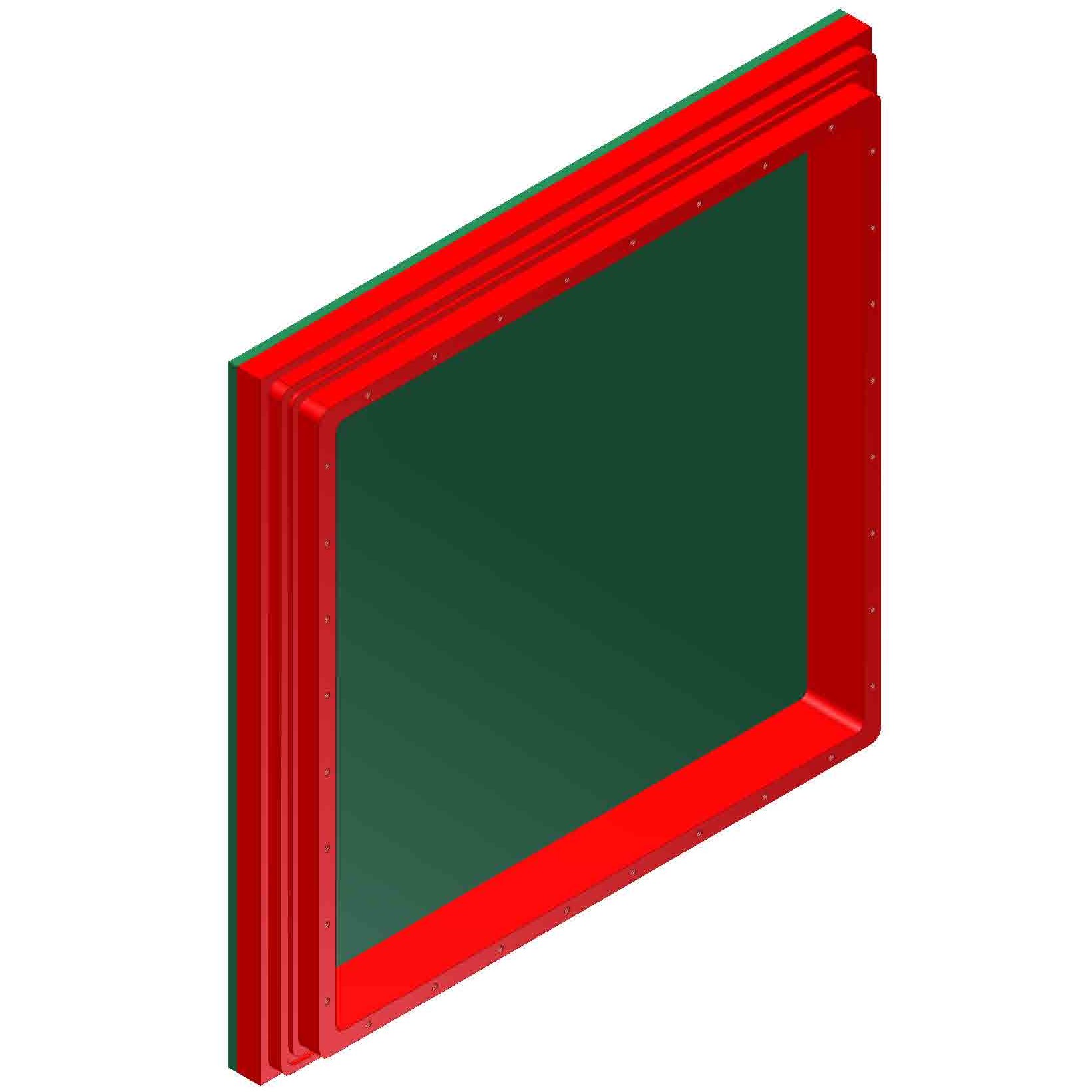
This shows the "readout module" that will be used for the tests.
The red part is the module back-frame.
The sealing surface includes an o-ring groove(1.76mm).
The back-frame also includes the strong section with threaded holes (~3mm).
 pdf
pdf
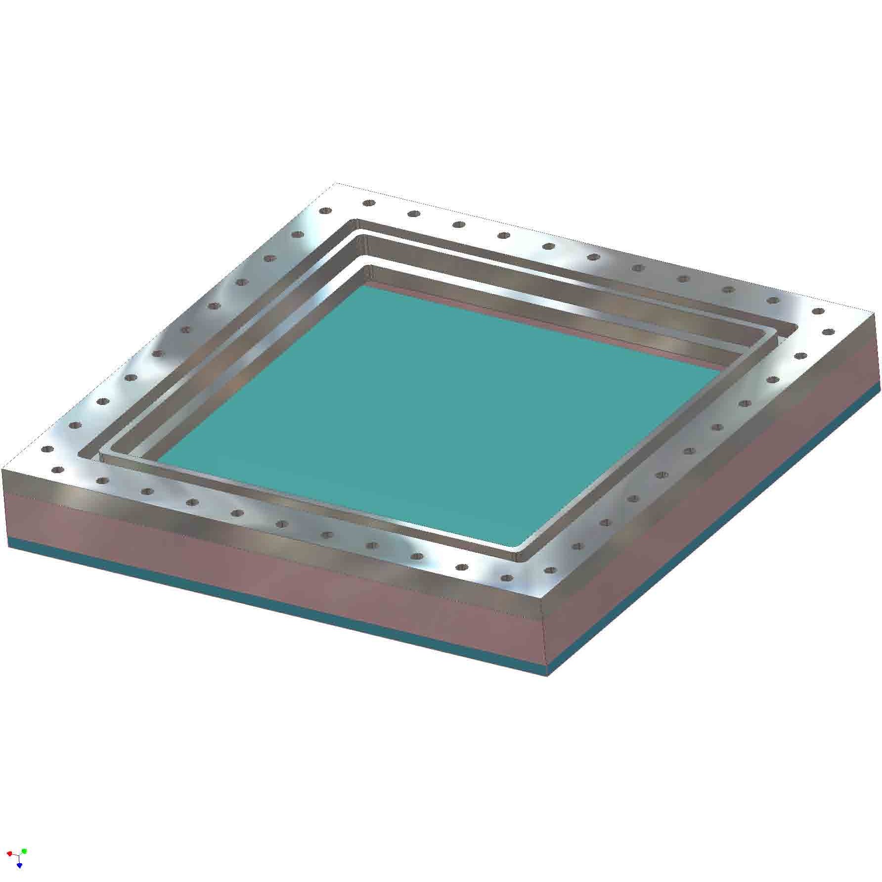
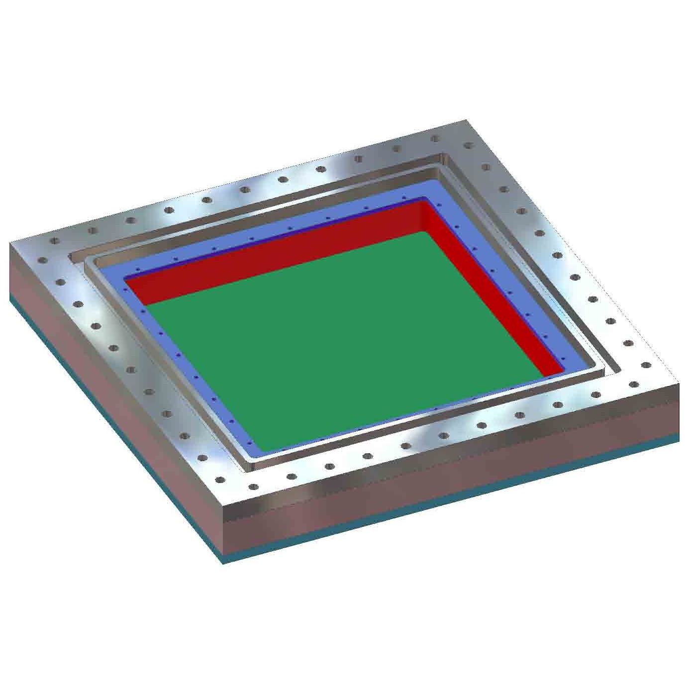
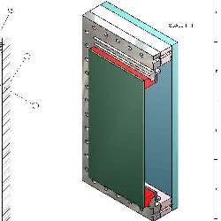
Below are 5 figures showing one configuration:
with the captured gas "outside the chamber" and
the pad-board exposed to air.
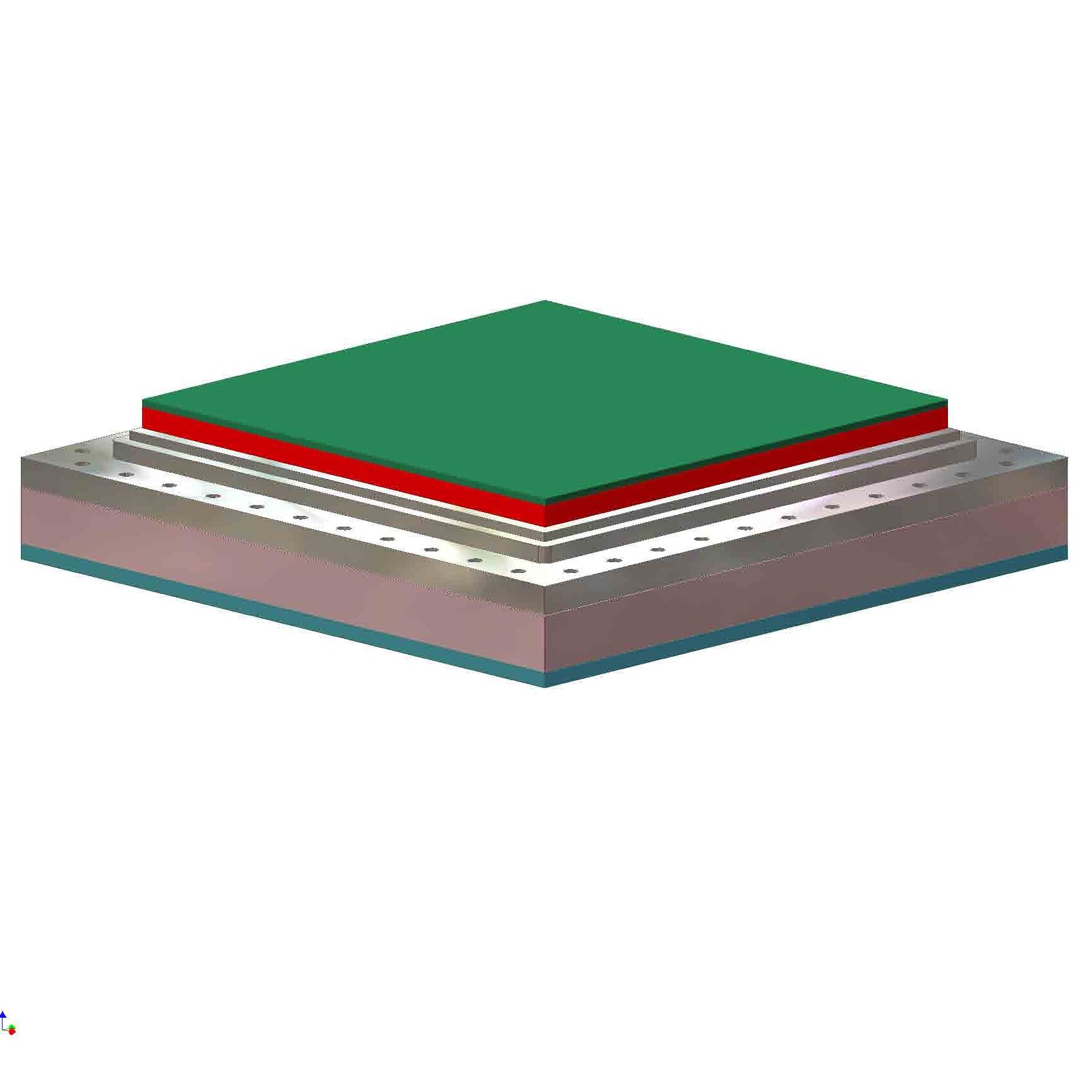
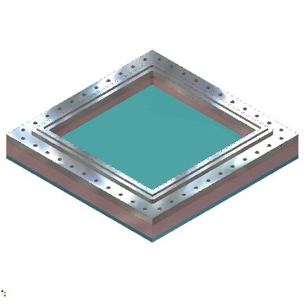
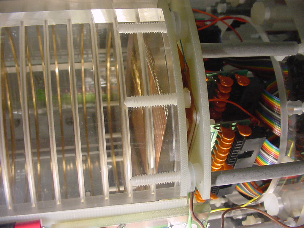
The 1st figure shows the mounting box, without the module module installed.
The rim is a model of the mounting surface on the large-prototype endplate.
The sealing surface is in the x-y plane and is the innermost surface in that plane.
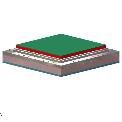
The 2nd figure shows the module in place on the mounting box.
In the 3rd figure, we are looking at the bottom
with the cover-plate removed.
The is the inside of the captured gas volume in this configuration.
The bracket is used
to pull the readout module back-frame and thus compress the o-ring.
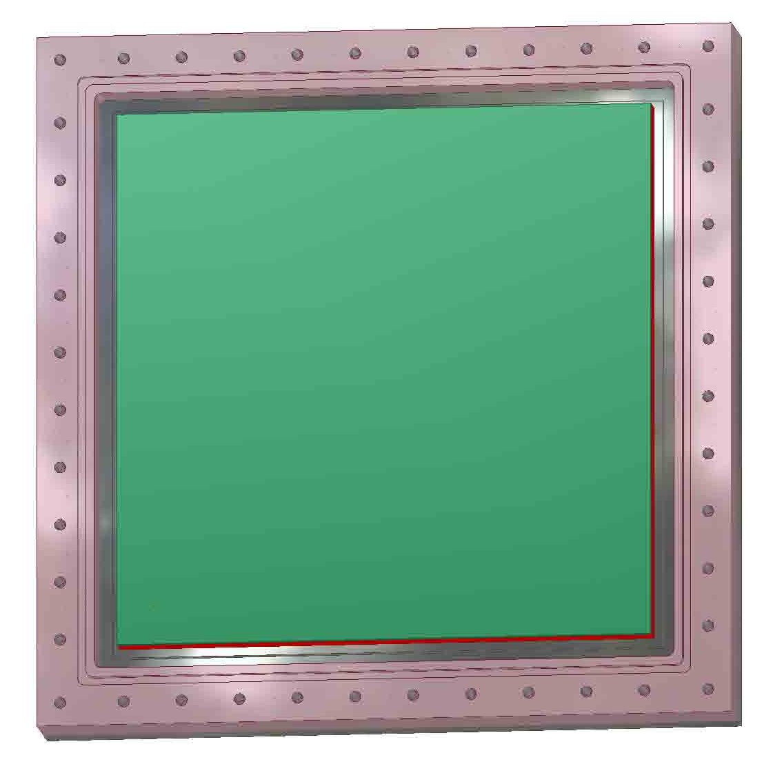
The 4th figure again shows the bottom view, but with the bracket removed to expose the back of the readout module back-frame.
The 5th (last) figure shows a cut-away of the assembly for this configuration.
 pdf
pdf
 pdf
pdf
 pdf
pdf
 pdf
pdf
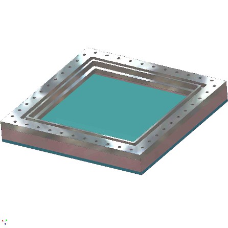
In a second configuration, the captured gas is on the
pad-board side of the module
while the "outside of the chamber" is exposed to air.
This is achieved with the same parts by flipping the spacer and cover-plate to the other side of the endplate.
Again, the 1st figure shows the mounting box, without the module installed.
The sealing surface of the "endplate" is facing down and can not be seen.
Again, the 2nd figure shows the full assembly with the module in place on the mounting box.
The 3rd figure also shows the top (air side) of the assembly but with
the bracket removed to expose the back of the
readout module back-frame.
In the 4th figure we are looking at the bottom
with the cover-plate removed.
The is the inside of the captured gas volume in this configuration.
This exposes the readout module pad-board that will be in the gas volume.
The 5th (last) figure shows a cut-away of the assembly for this configuration.
 pdf
pdf
 pdf
pdf
 pdf
pdf
 pdf
pdf
 PRESENTATIONS
 (purdue)
 (pdf)
(pdf)
 (pdf)
(pdf)