Muon HV Bleeder Hardware
Address Map
Base address: Set by switch on Muon Bleeder Relay VME Control Card, A[15..4]
Address Decoder: A[3..1] decodes functions on the VME control card
A[3..1] R/W Description of Function
0x0 R Read Board ID (constant set in Altera chip)
0x1 R Read Board ID
0x2 R Read port0(en[0], pwr[0], dis[0])
0x2 W Write dis value for port0: 1 shunts, 0 stops shunting
0x3 R Read port1(en[1], pwr[1], dis[1])
0x3 W Write dis value for port1 (D0 is 1 or 0)
0x4 R Read port2(en[2], pwr[2], dis[2])
0x4 W Write dis value for port2 (D0 is 1 or 0)
0x5 R Read port3(en[3], pwr[3], dis[3])
0x5 W Write dis value for port3 (D0 is 1 or 0)
0x6 R Read port4(en[4], pwr[4], dis[4])
0x6 W Write dis value for port4 (D0 is 1 or 0)
0x7 R Read port5(en[5], pwr[5], dis[5])
0x7 W Write dis value for port5 (D0 is 1 or 0)
Additional notes
To shunt high voltage to ground and bleed the muon hv, set DIS to 1.
To stop bleeding the muon hv, set DIS to 0.
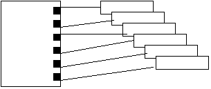
Each Muon HV Bleeder Relay VME Control Card has 6 ribbon cable connectors.
Each ribbon cable carries a single DIS, PWR, and EN signal.
Each ribbon cable connects to one Muon HV Bleeder.
Each Muon HV Bleeder receives one ribbon cable input from the VME control card.
The DIS signal driven by the ribbon cable controls 8 HV channels which are either all on
To Muon Chambers

Muon HV Bleeder Relay
VME Control Card Muon HV Bleeders Side view of one SHV
connector on Muon HV Bleeders To High Voltage system


