Box
1
Box
1CESR-CLEO HV Interface Hardware
Address Map
Base address: Set by switch on HV Interface board, A[15..4] = (0x0510)
Address Decoder: A[3..0] decodes functions on the VME board
A[3..0] R/W Description of Function
0x0 R Read Board ID (constant set in Altera chip)
0x1 R Read Board ID (ID = 46 = 0x2E)
0x2 R Clears counter; Reads csr[3..0]
CSR 0 = Timeout Clear
CSR 1 = Timeout Set
CSR 2 = CESR INHIBIT (Output)
CSR 3 = Timeout has occurred (FAIL)
CSR 4 = CESR HV ENABLE (Input)
W D0 = 1 forces a clear of timeout (nFAIL = 1)
W D1 = 1 forces a timeout (nFAIL = 0)
W D2 = 1 sends an inhibit to CESR
0x3 R Read Watchdog Timeout (in seconds)
W Write Timeout value (in seconds)
NOTE: Setting TO value to 0 will always generate a TO
Additional notes
There are 3 ways to Timeout:
1) The timer counts up to the Timeout value, after which it will force a Timeout
FAIL condition.
2) Writing a Timeout value of zero will always generate a Timeout FAIL
3) Write to A[3..1] = 2 and D[2..0] = 0x2 (Set TMO SET bit)
To clear the Timeout FAIL:
1) Write a nonzero Timeout value to the Watchdog Timer.
Write to A[3..1] = 2 and D[2..0] = 1
(Set TMO CLR bit to clear the previous FAIL)
You also need to write A[2..0] = 2, D[2..0] = 0 to clear the CSR and release
the TMO clear bit. To start the timer again.
(At this stage, you may also set the INHIBIT).
To keep the Watchdog Timer from Timing Out, you need to hit it:
1) Clear counter by reading A[3..0] = 2.
You can double-check this value to see the CESR HVEnable status and
also double-check that there is no Timeout FAIL.
Note: The INHIBIT is cleared by the assertion of FAIL. If the HV Server stops running for some reason and the watchdog times out, not only is the FAIL asserted, but the INHIBIT is also released.
The OLD HV enable signal worked like this:
CESR CLEO HV
Box
1
HV

 Enable Box
2
Enable Box
2
Box 3
The NEW HV enable signal works like this:
CESR CLEO HV


 Box 1
Box 1


 HV
Box 2
HV
Box 2
Enable FAIL
Box 3
 INHIBIT
(to CESR) CESR-CLEO
HV Interlock
In a FAIL condition, the CESR HV ENABLE line connects to the CLEO HV ENABLE line.
The logic is as follows. If the CLEO HV program stops hitting the watchdog timer, the interlock board will generate a FAIL condition which connects the CESR HV ENABLE to the CLEO HV. If the CLEO HV Server can’t hit the watchdog, it means that the CLEO HV Slow Control system is no longer capable of controlling that status of its HV (turning the HV ON and OFF). The FAIL condition allows CESR to control the HV for us.
During normal running, the HV Server will continually be hitting the watchdog timer (reading the CSR) to keep the Interlock board from timing out. This will keep the control of the HV in the hands of the CLEO HV Slow Control. Should the CLEO HV Server break and stop hitting the watchdog, the CLEO HV control will pass into the hands of CESR (through the HV ENABLE line).
The other line shared by the CESR-CLEO HV Interlock and CESR is the INHIBIT. The INHIBIT can keep CESR from filling, etc. while the HV system is ramping or is in some other intermediate state.
What happens when you first turn the CESR-CLEO HV Interlock board on?
fbff0510: 002E ADR[0] = Board ID = 0x2e = 46
fbff0512: 002E ADR[1] = Board ID = 0x2e = 46
fbff0514: 0018 ADR[2] = CSR = 0x18
CSR 0 = 0 = Timeout Clear
CSR 1 = 0 = Timeout Set
CSR 2 = 0 = CESR INHIBIT (Output)
CSR 3 = 1 = FAIL
CSR 4 = 1 = CESR HVEnable: no cable plugged in
fbff0516 0000 ADR[3] = Timeout Value = 0
What happens after a Timeout Fail?
Same as power-up conditions above with one exception:
Timeout value remains unchanged.
Example: If timeout value was 0x10 before the Timeout then fbff0516 will read
back 0x10 after the timeout as well.
What happens if the power to the CESR-CLEO HV Interlock crate is turned off?
The Server running on that ppc will go away. I don’t know how this affects us
or how to tell when this happens yet.
The CESR HVENABLE switch is CLOSED which means the CESR and CLEO
lines are connected. (There is 0 resistance between the centers of the two
connectors.
The CESR INHIBIT switch is also CLOSED so the resistance between inner and
outer barrels on the connector is 0.
We will not be able to read out these values!!!!
What are the values of the switches INHIBIT and HVENABLE switches?
Power is ON:
FAIL = 1 R = 0 (R is the resistance between the centers of
FAIL = 0 R = the HVEnable connectors).
INHIBIT = 1 R = (R is the resistance between the inner and
INHIBIT = 0 R = 0 outer barrel of the connector).
Power is OFF:
FAIL R = 0
INHIBIT R = 0
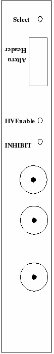
Front panel and LED’s
Select
LED flashes green whenever the board is addressed. There is
a 10-pin Altera header on the board for reprogramming
the Altera chip. It is accessible through the front panel HVEnable
is a green LED which is ON whenever FAIL is NOT asserted.
Therefore, it is on whenever CLEO has control over its own HV and
off whenever CESR has control over CLEO HV. INHIBIT
is a red LED which is ON when the INHIBIT relay is open and OFF
when the relay is closed.