Primary Charging Supply

The two power supplies at the top and bottom of the rack charge the capacitor bands in the two black 'Charging' supplies in the middle of the rack to about 650 volts. The HV transformer (in the oil tank) ratio of 85:1 charges the blumlein to 55kV. The white module on the face of the power supplies is the remote control interface.
The capacitor bank in the Charging supply
Triggering block in the charging supply. Kilovac relay connects to dump resistor. SCR thyristor to charge blumlein.
View of another charging supply
The 
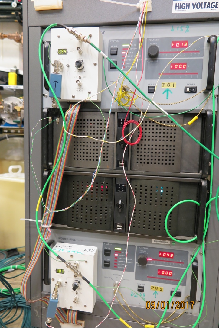
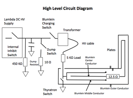
HV supply charges the capacitor bank in the Charging Supply to about 700V. 
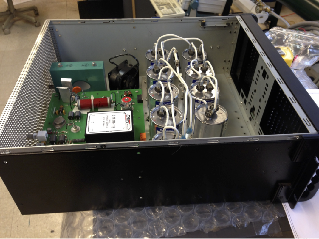
The cap bank is visible in the photo at the upper rignt. The capcitor bank is discharged throught the 
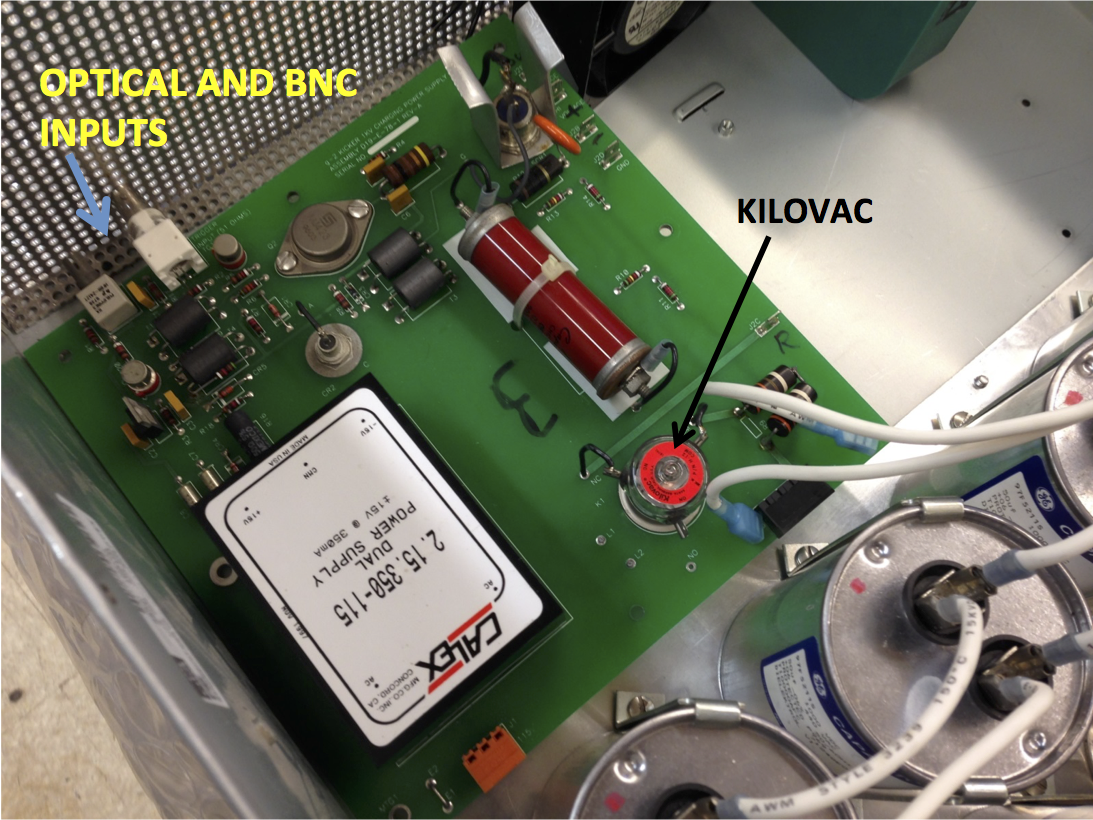
HV transformer when the thyristor in the charging supply is triggered. The kilovac relay and trigger inputs are indicated in the bottom left photo.

Circuit Diagrams

Photographs of the Guts

Reports

Components and POs

  1. Component List (docx) (Hirshman) and pdf
  2. Triggering multiplexer with fiber optics output - PO
  3. SEMTECH Fast Recovery High Voltage Rectifier Assembly
  4. Analog Power Meters PO (xls) and pdf
  5. Connector PO (xls) and pdf
  6. Diode PO (xls) and pdf
  7. HV transistor PO
  8. capacitors PO
  9. Gigavac PO
  10. PCB PO
  11. SCR PO
  12. Pearson Current monitor PO and pdf
  13. capacitors PO