TPC Large Prototype Endplate Cornell Instructions Page
2007-04-02 coordinate files for CMM measurements
Links below provide files describing the required CMM measurement points.
The first number give the current status of the "oversize" of the part.
Then the coordinates for 372 measurements are described in the table.
Column 1,
X coordinate of the measurement.
Column 2,
Y coordinate of the measurement.
Column 3,
Z coordinate of the measurement.
Column 4,
expected X value of the measurement. This will differ from column 1 if this is an "x measurement".
Column 5,
expected Y value of the measurement. This will differ from column 2 if this is a "y measurement".
Column 6,
expected Z value of the measurement. This will differ from column 3 if this is a "z measurement".
Column 7,
is left blank to allow the measured value to be inserted.
Columns 8, 9, 10
are internal numbers to calculate columns 5, 6, 7.
Columns 11, 12, 13
are descriptions of the measurement.
Note that "decreasing x" (for example) in colunm 13 (or M) indicates that the measurement is to be made with the probe traveling in the "decreasing x" direction.
Select the
Excel file
, or the
text file .
The original
Word file
is provided for reference.
Updated 2007-04-09
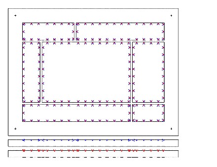
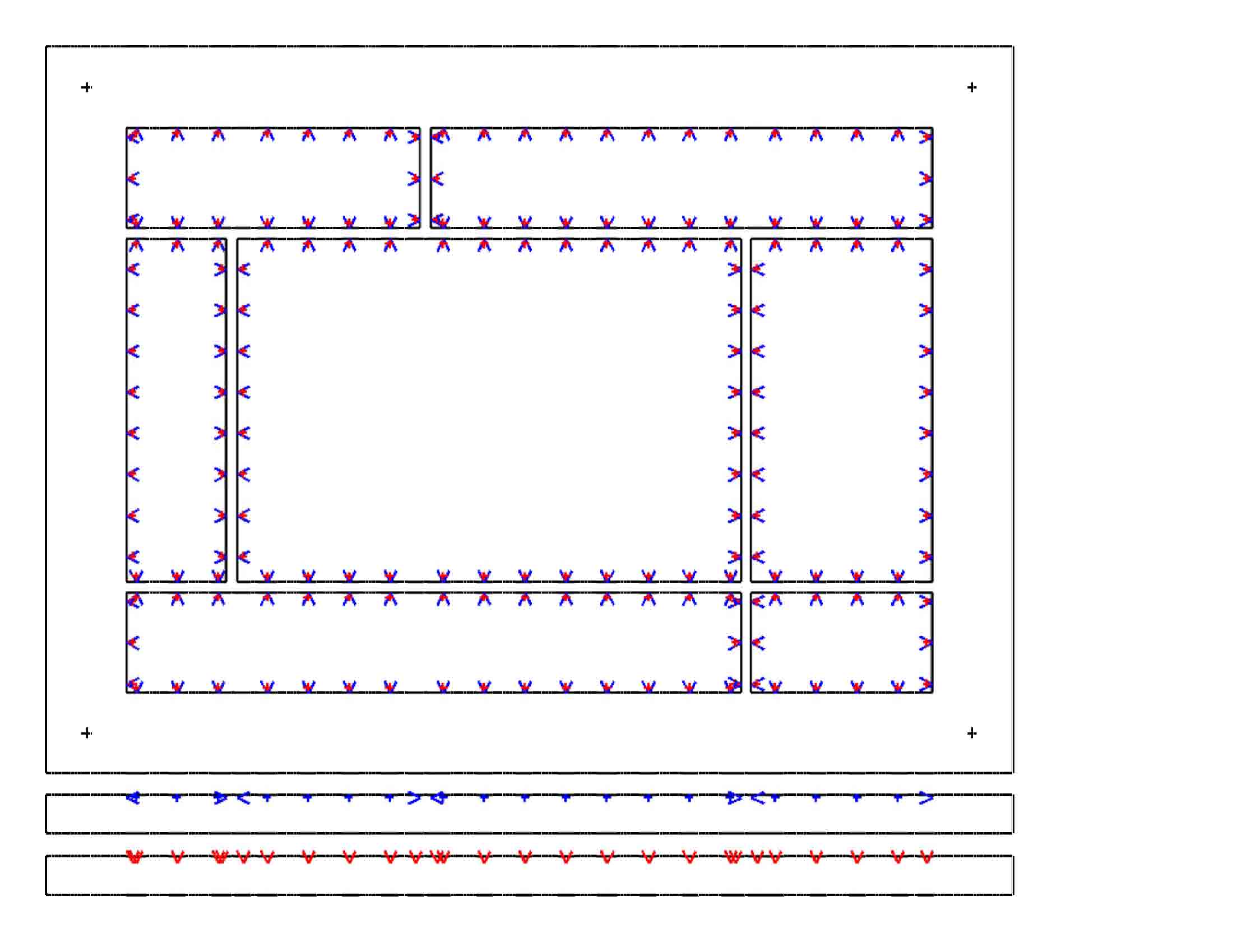
A map of the measurement coordinates is shown below.
The map has been generated from the text file linked above; it proves the measurements at located correctly.
Blue arrows indicate the x,y measurements. Red crosses indicate the z measurements. Select the figure for a larger jpg view. Select the text "pdf" to download a pdf file. (The program that generates this figure will be the starting point for a program to analyze the CMM results.)
 pdf
pdf
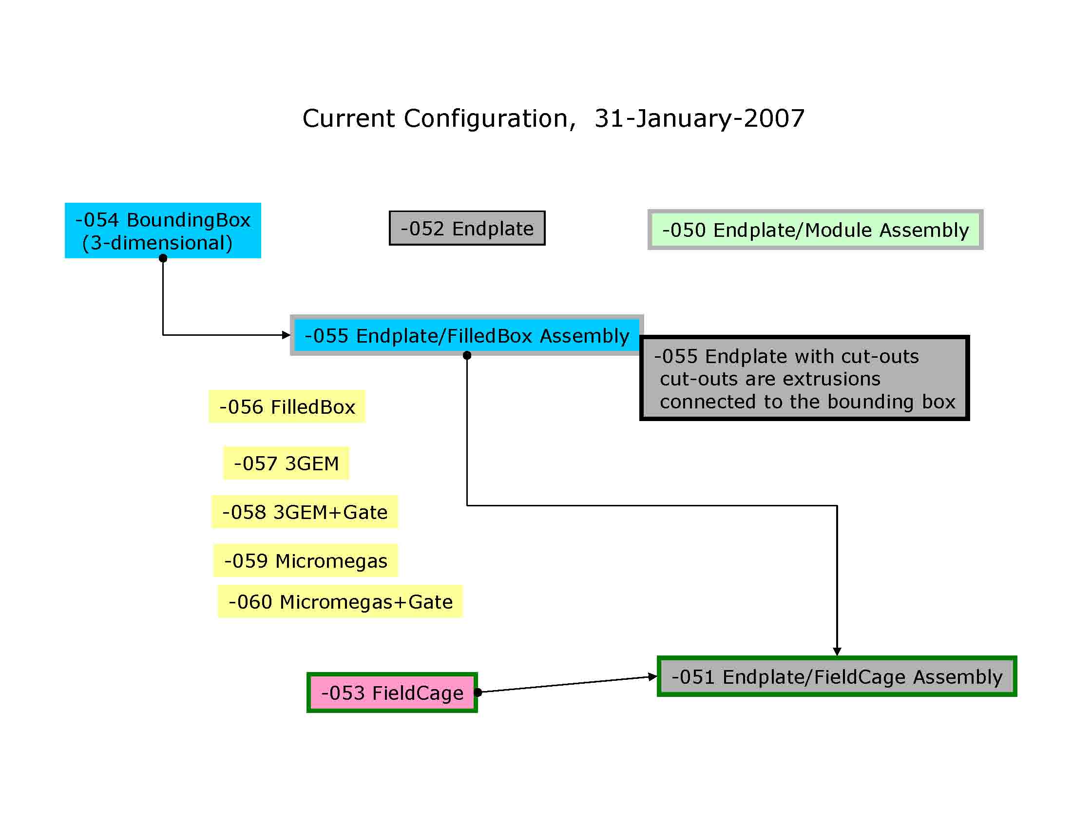
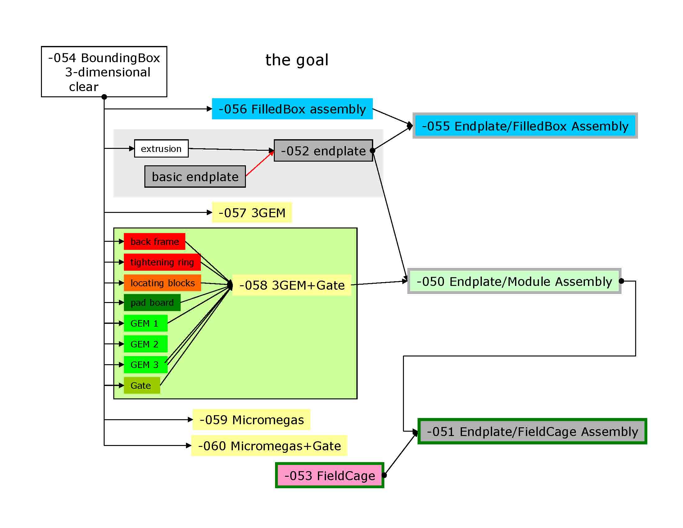
2007-02-22 Drawing organization
This is internal Cornell drawing organization, before the use of the parameter list.
 pdf
pdf
 pdf
pdf
 PRESENTATIONS
 (purdue)
 pdf
pdf