 EPS
EPS
 EPS
EPS
Model includes all auxiliary holes. This model is from before placing a dowel hole at zero degrees (2008-02-14), but you won't be able to see the difference.
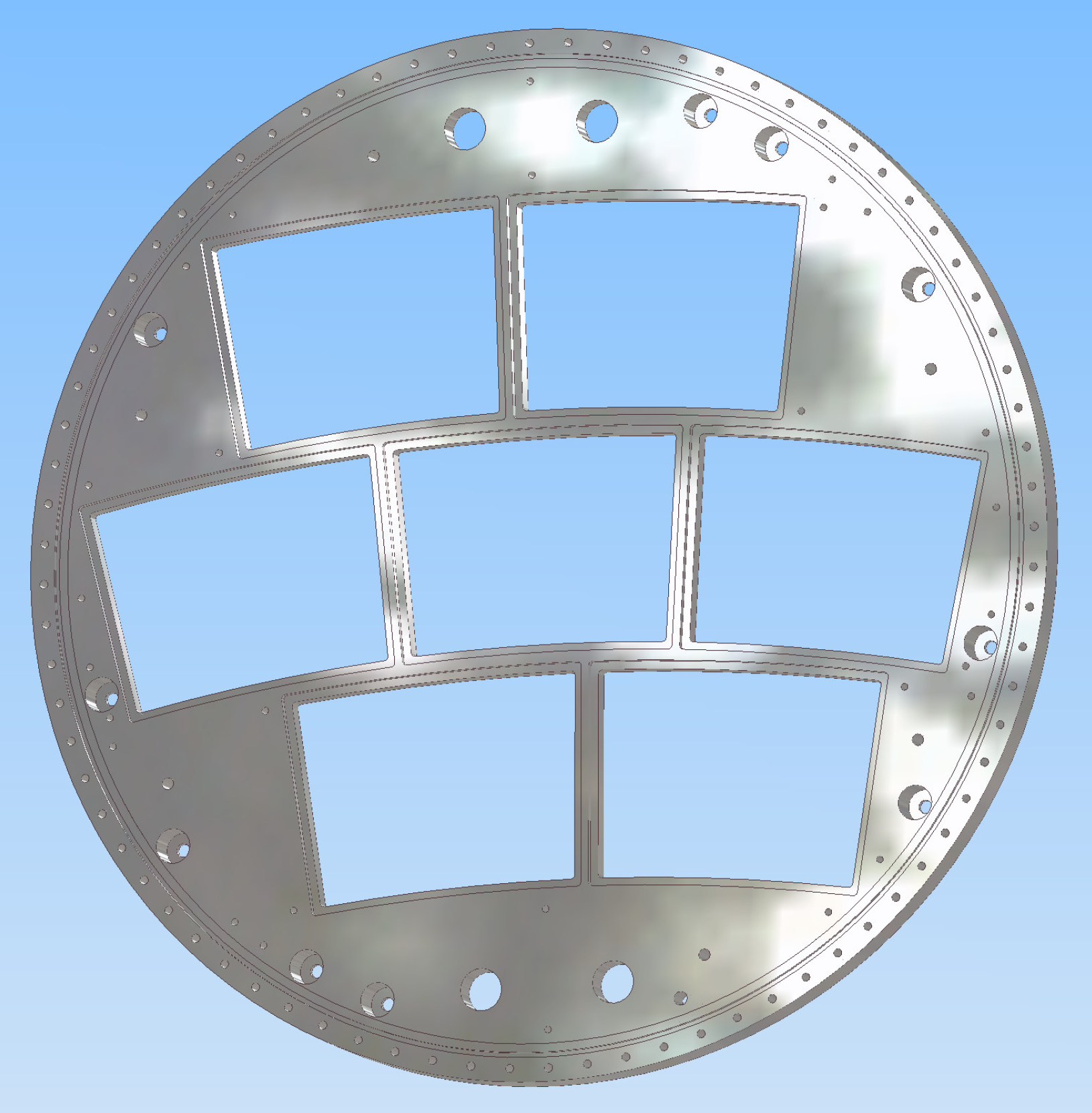
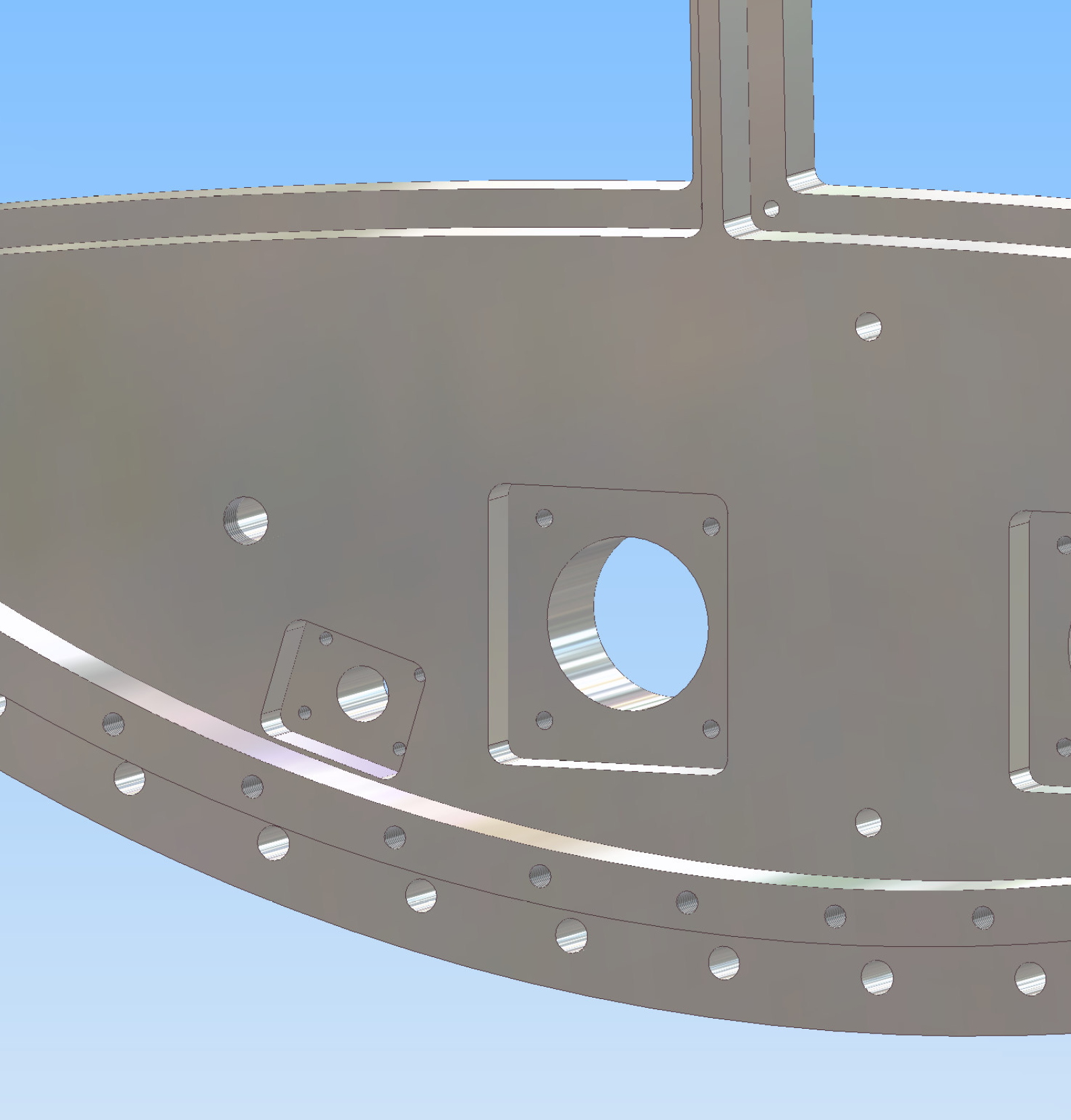
Model includes all holes as in the first production run at Cornell.
(20080205)
 (20080128)
Lastest model includes a larger clearance central opening.
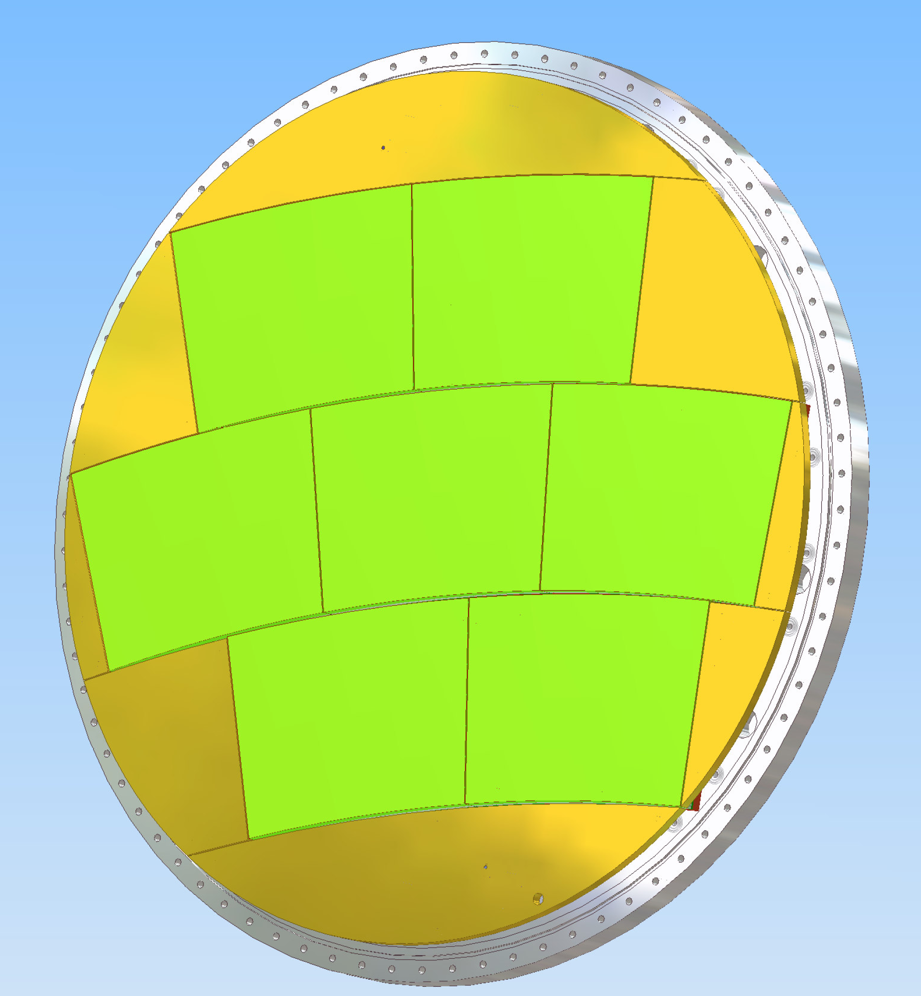
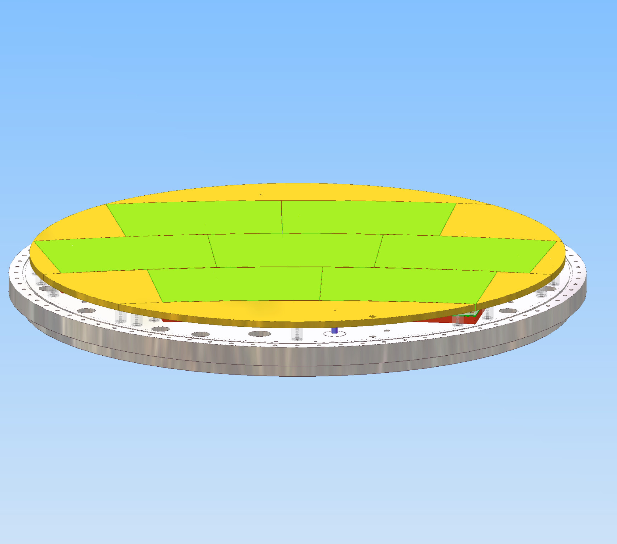
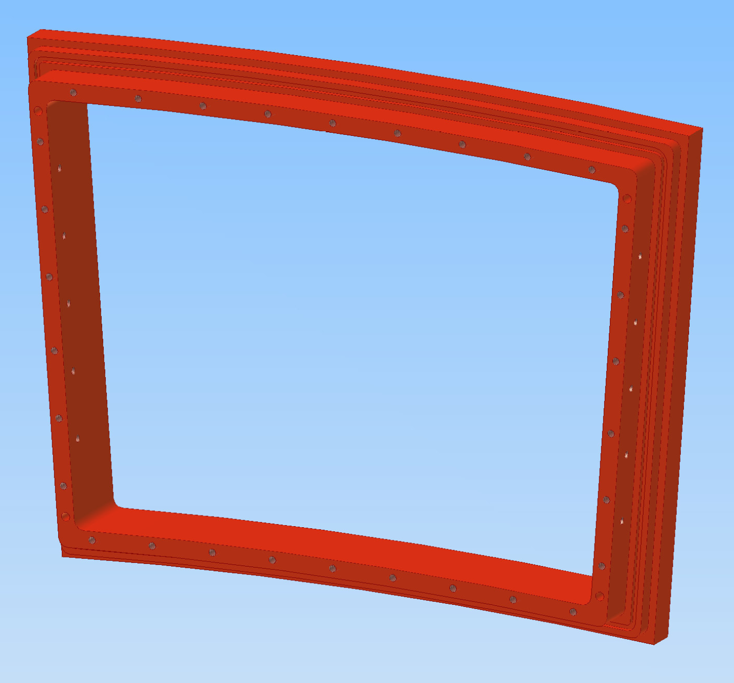
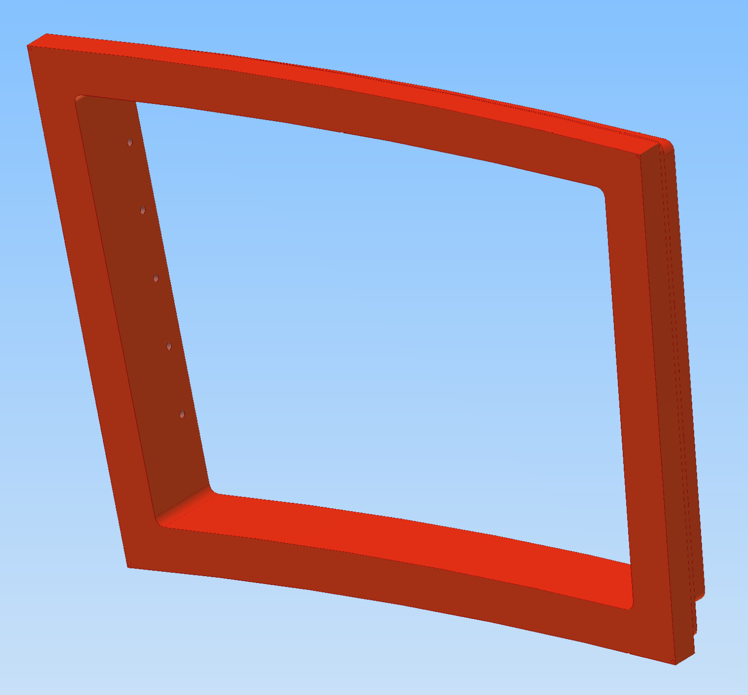
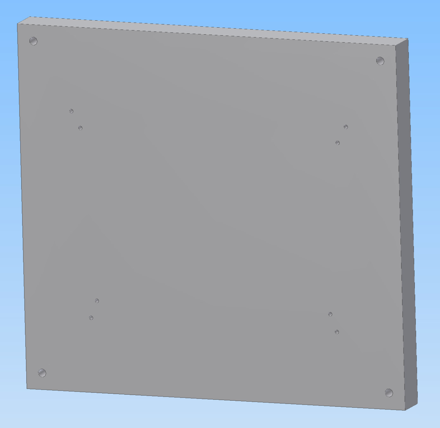
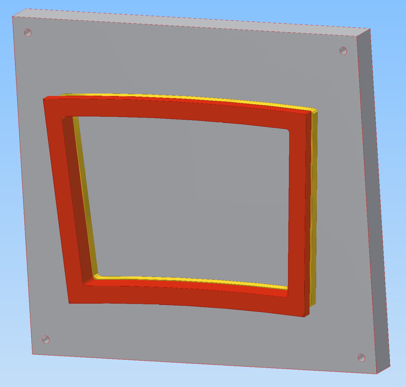
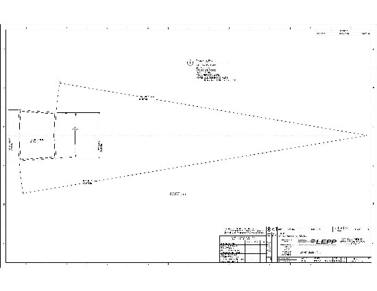
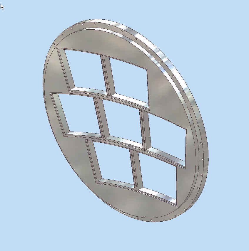
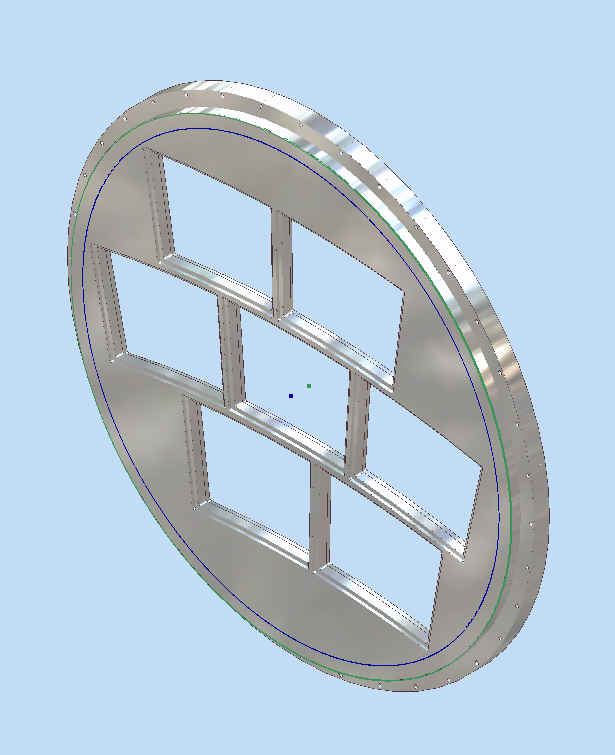
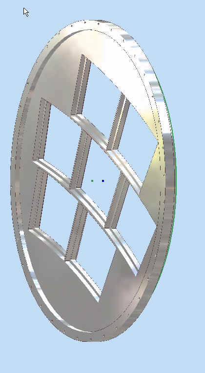
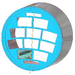
The first figure shows the jig alone. The second figure shows the BackFrame, and Mounting Bracket, mounting on the jig.
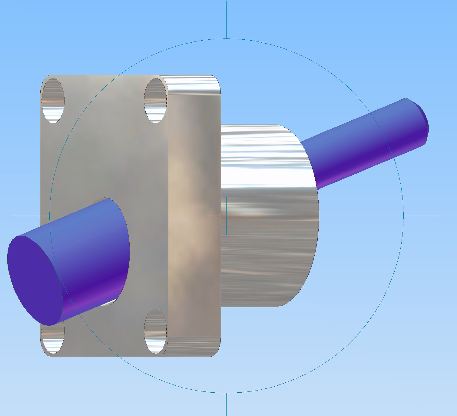
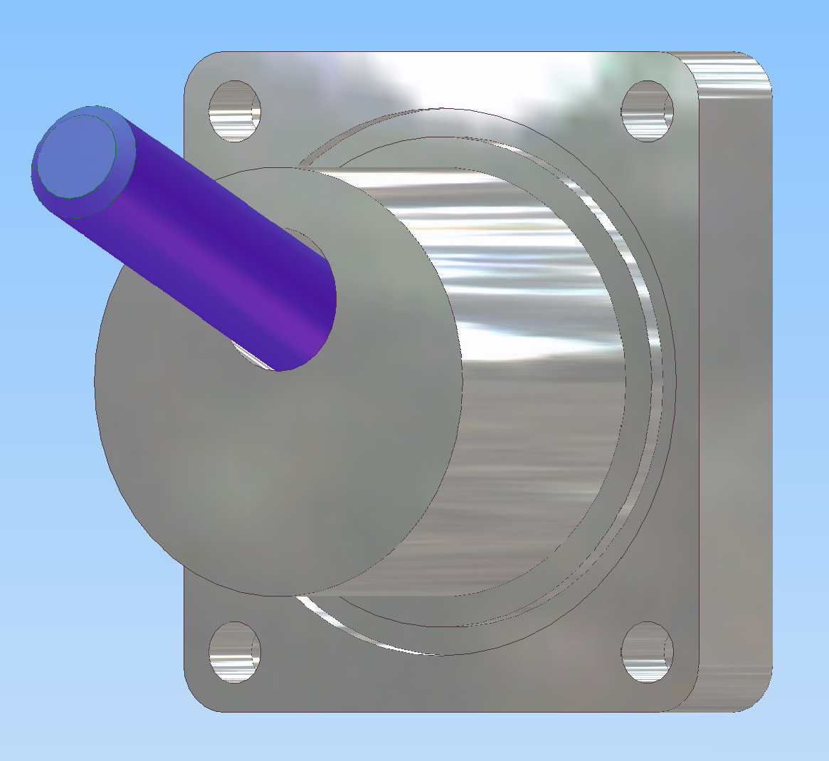
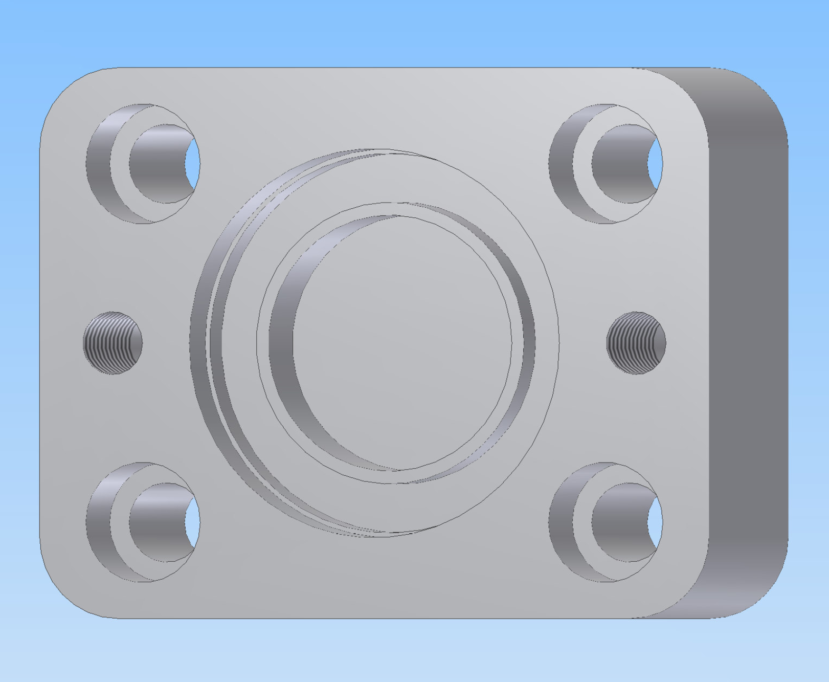
This is a model made at Cornell and is to show the concept only. The outer flange, 4 corner mounting holes, and o-ring are in agreement with Victoria specifications.
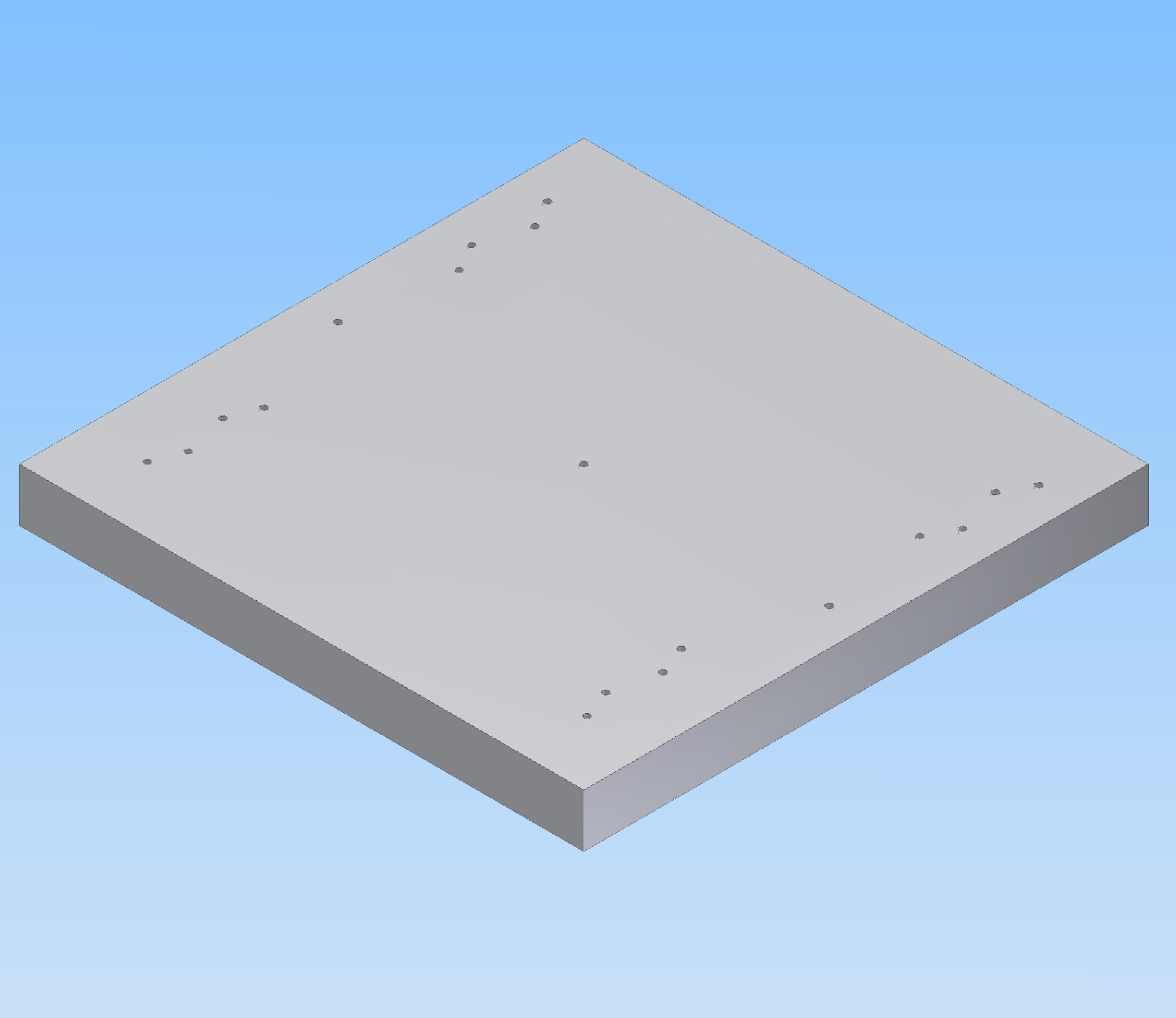
This is not part of the TPC assembly. Itis a test block used to certify the trig-function utilities of the machine.
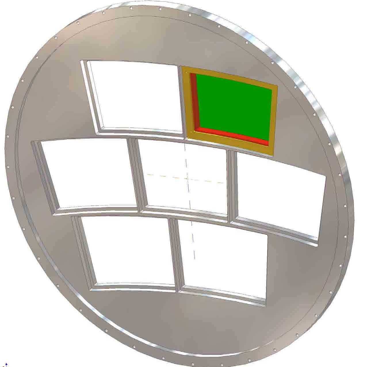
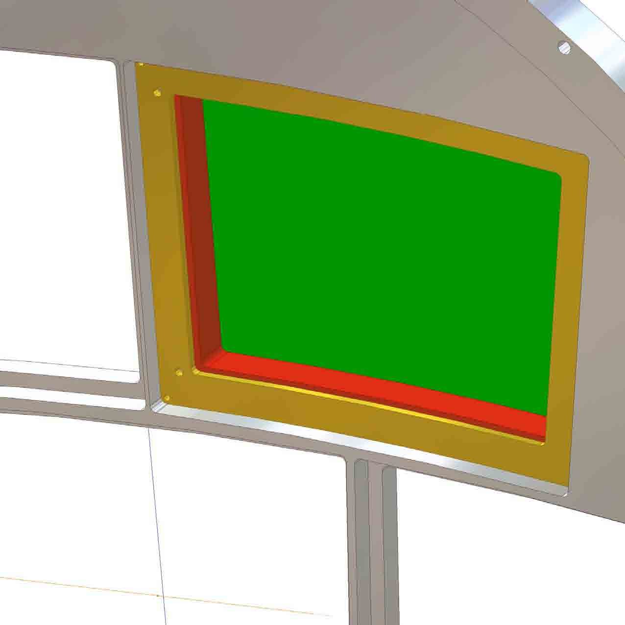
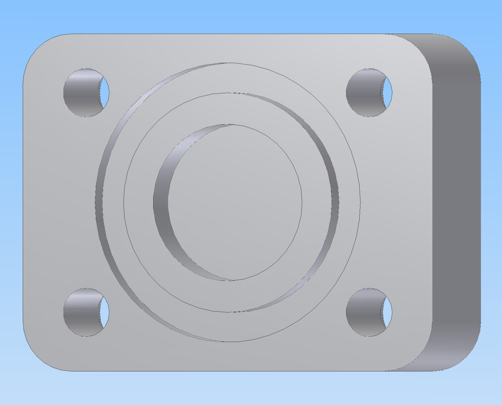
This is used to cover Victoria Light Insert holes when not used. It is also used as a starting piece for mounting and installing monitoring devices (temperature and pressure).
![]()
![]()
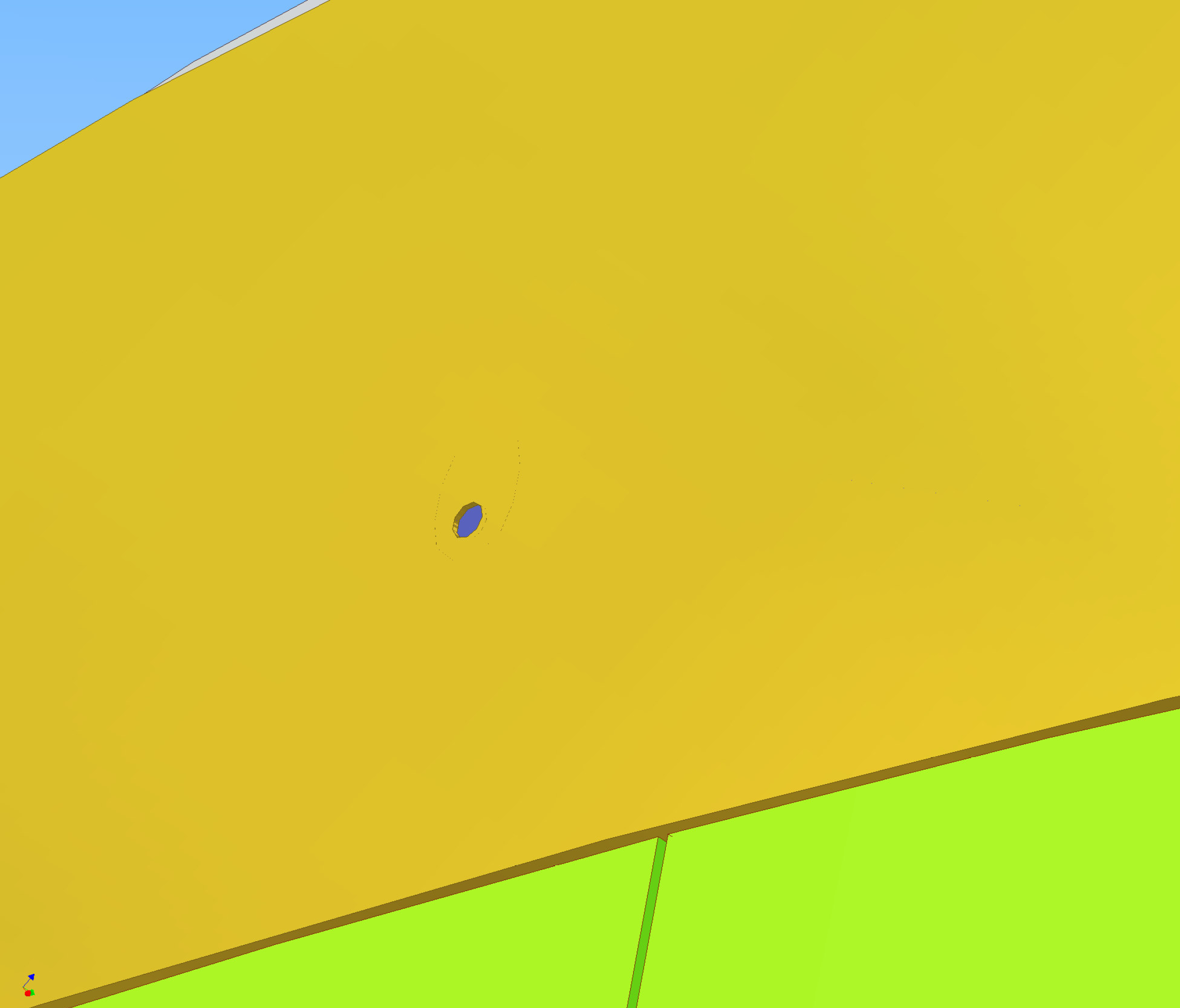
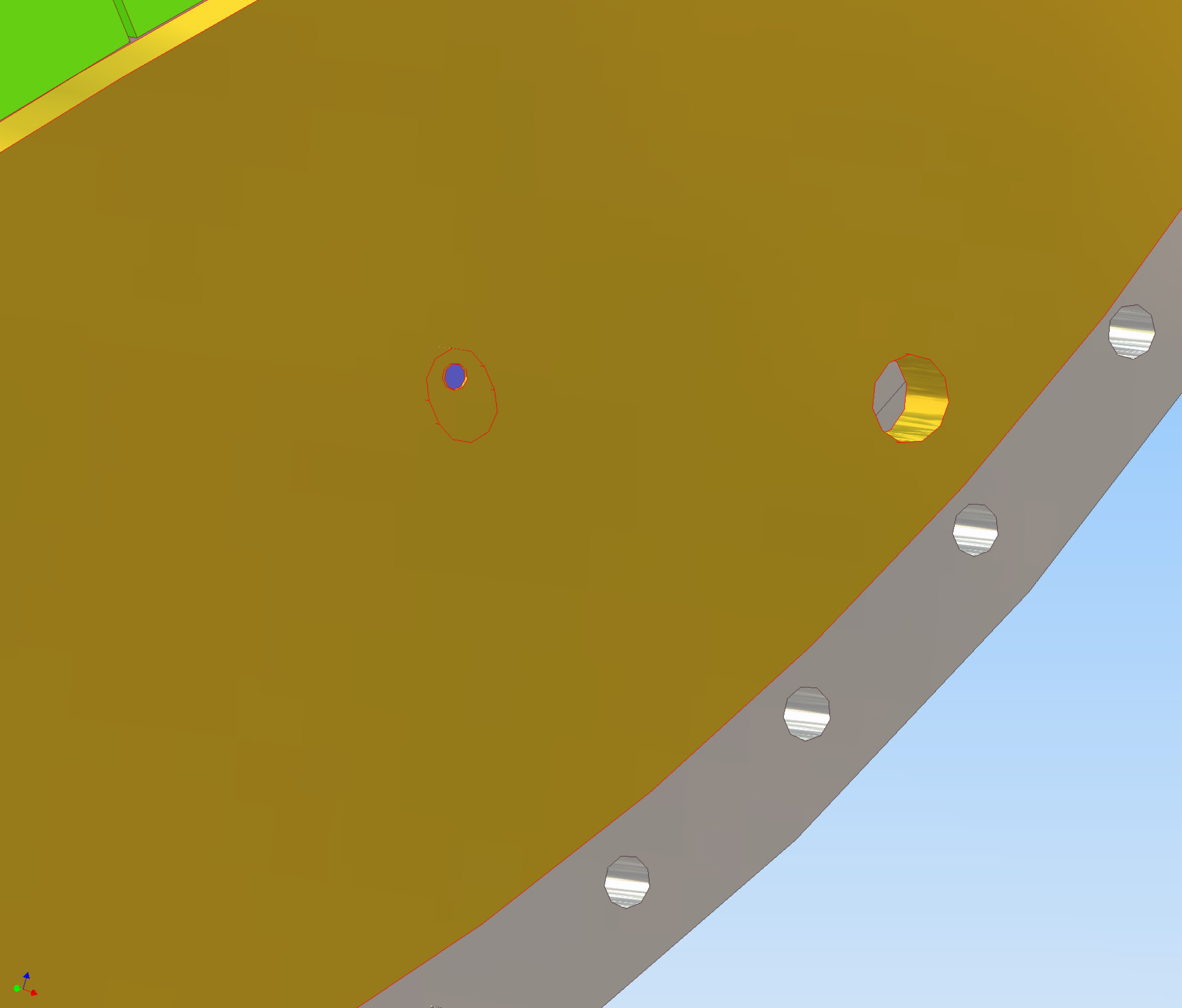
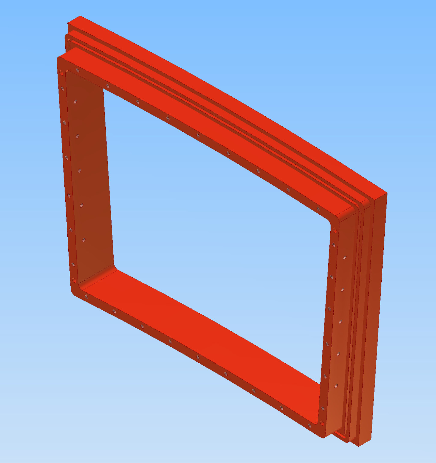
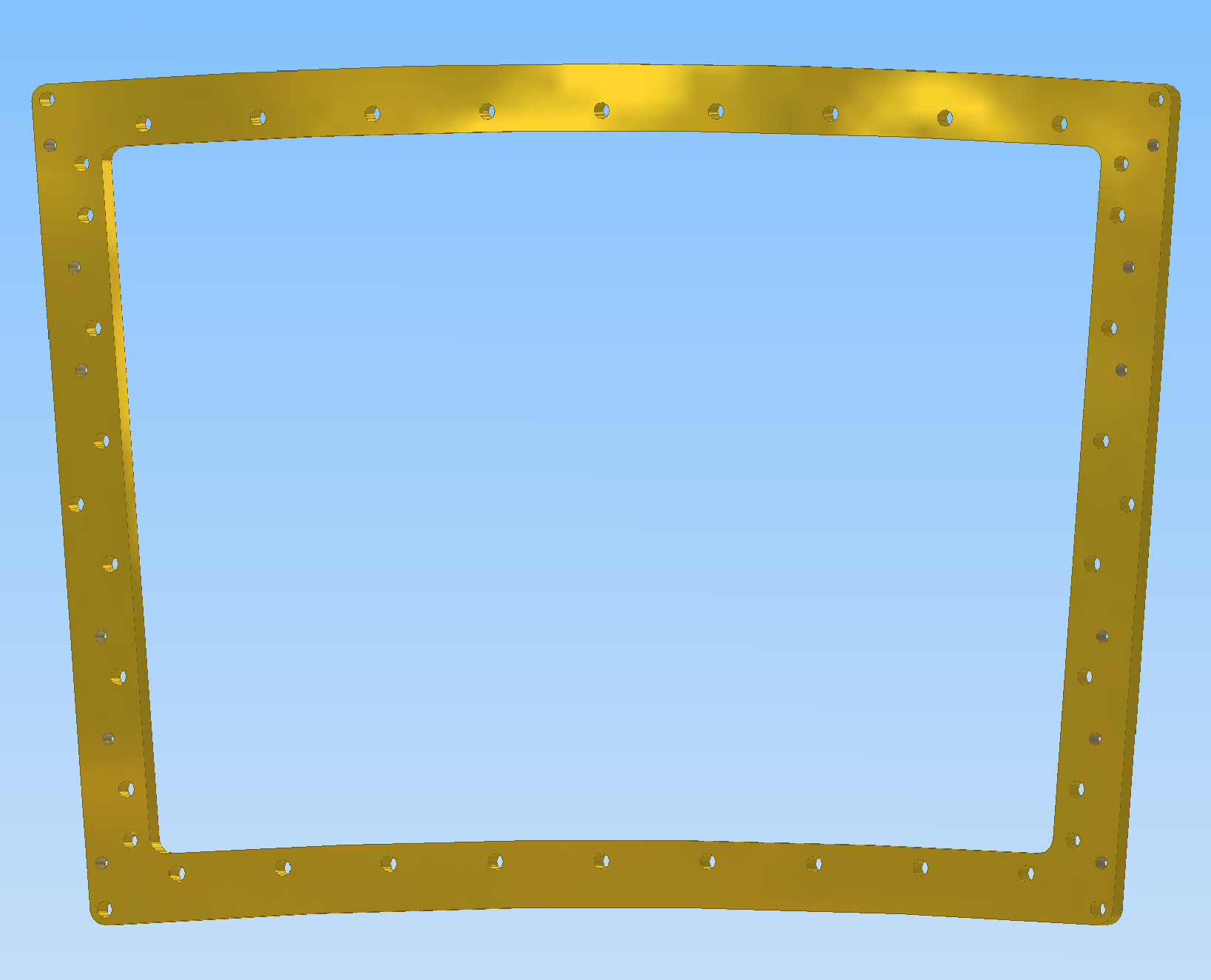
Note: the central hole is to be cut through when the lens is mounted. The first figure shows the side toward the endplate, with a central hole and an o-ring groove. The second figure shows the outside, with a central hole, and mounting for a lens.
Use the 6080-111 assembly for the Field Cage Termination model figures.
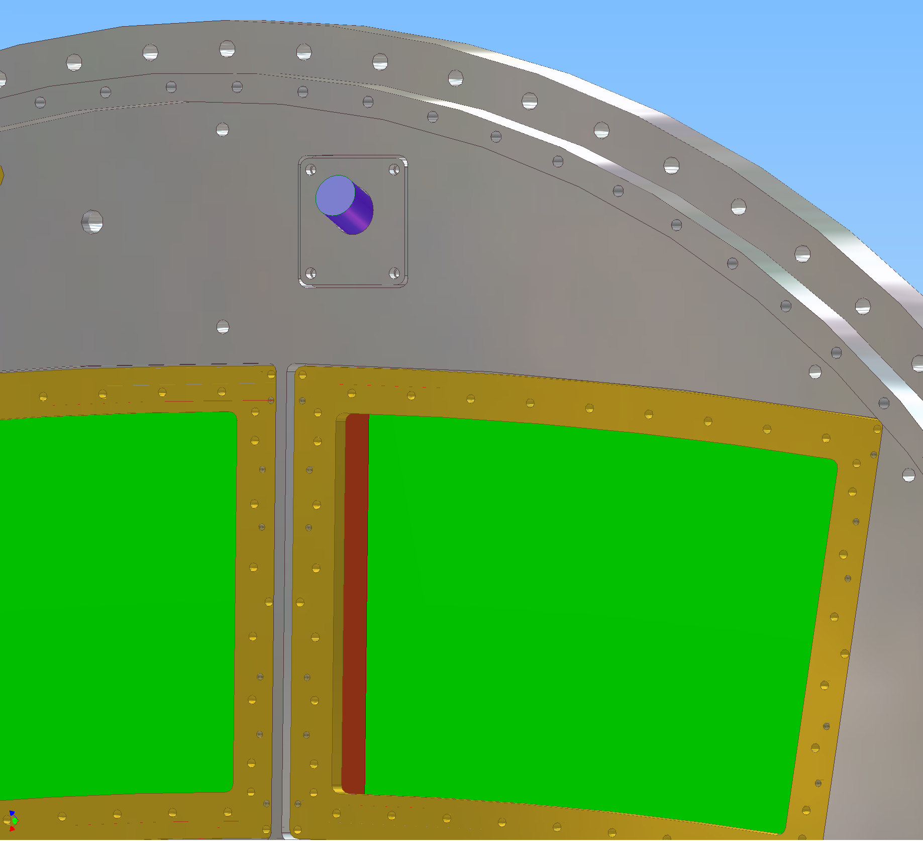
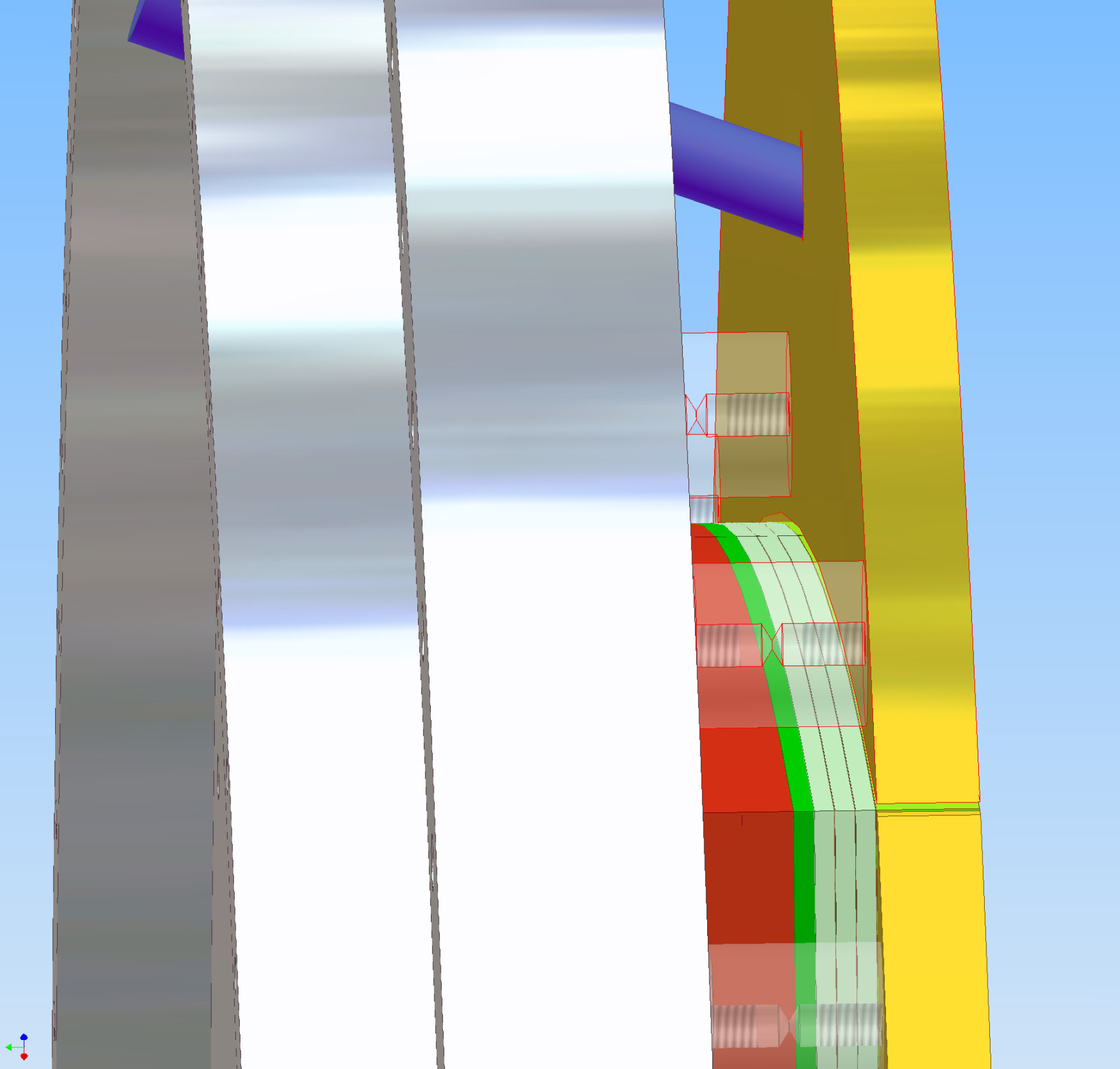
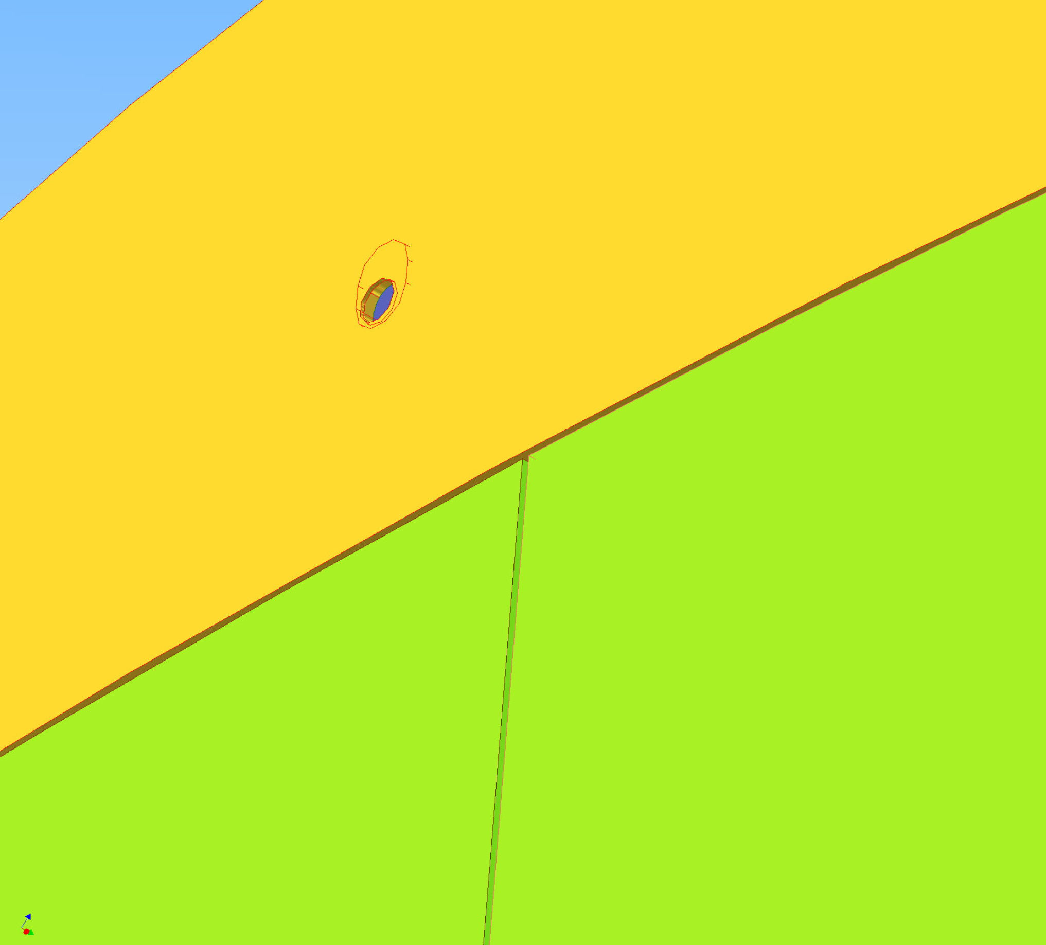
Model includes VictoriaLightInsert, FieldCageTermination mounting, FieldCageTermination HV holes, gas holes, MountingBracket retaining holes, strain relief on the MountingBrackets.
Models from 2008-01-16 do not have strain relief on the MountingBrackets.
Models from 2008-01-11 have the wrong clearance hole in the FieldCageTermination for the VictoriaLightInsert.
Model is missing entry for pressure and temperature monitors, and laser access.
(20080123)
(20080116)
(20080111)
 pdf
pdf
 pdf
pdf
This is the latest full assembly. It is with 3GEMG. It is missing the FieldCgaeTermination and many other things.
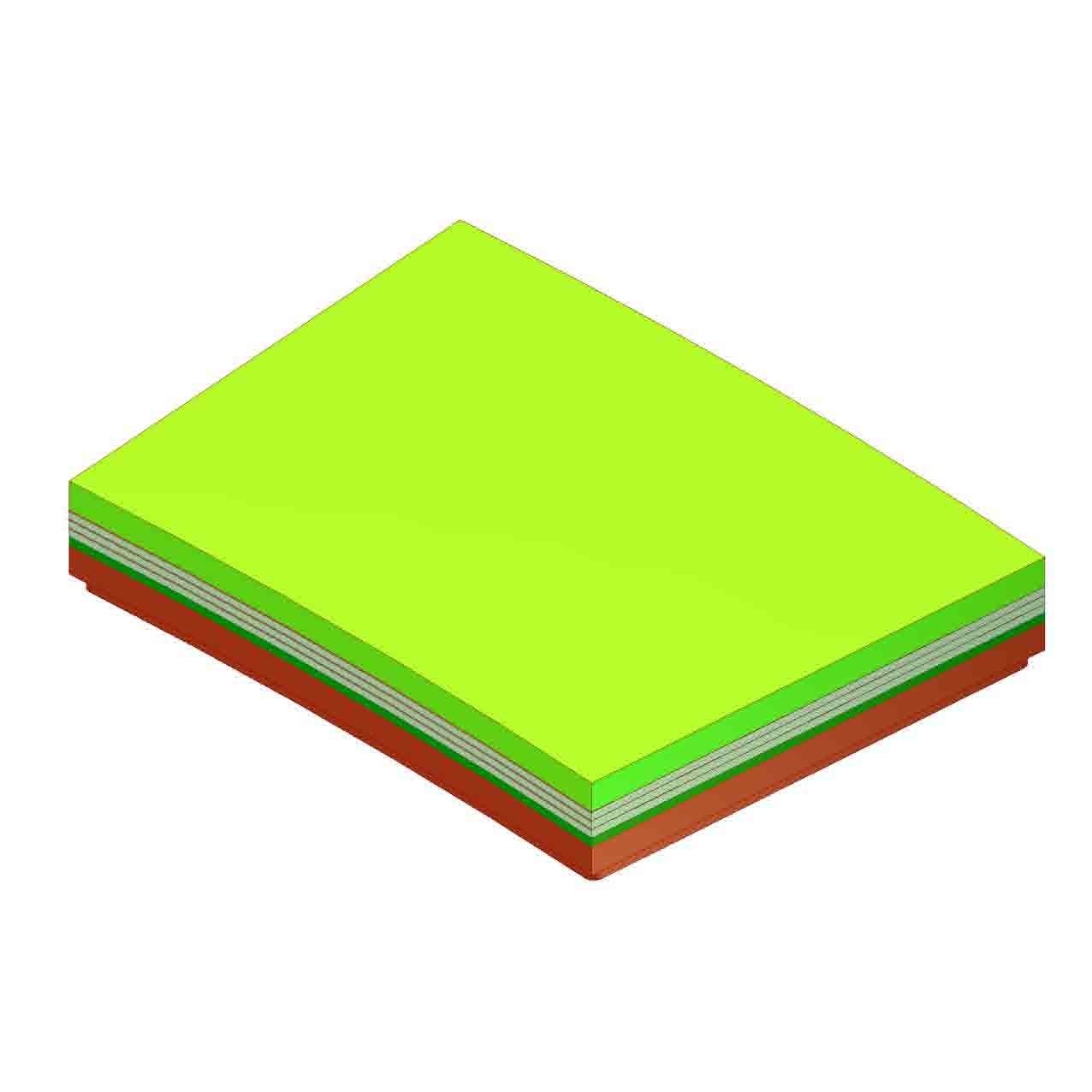
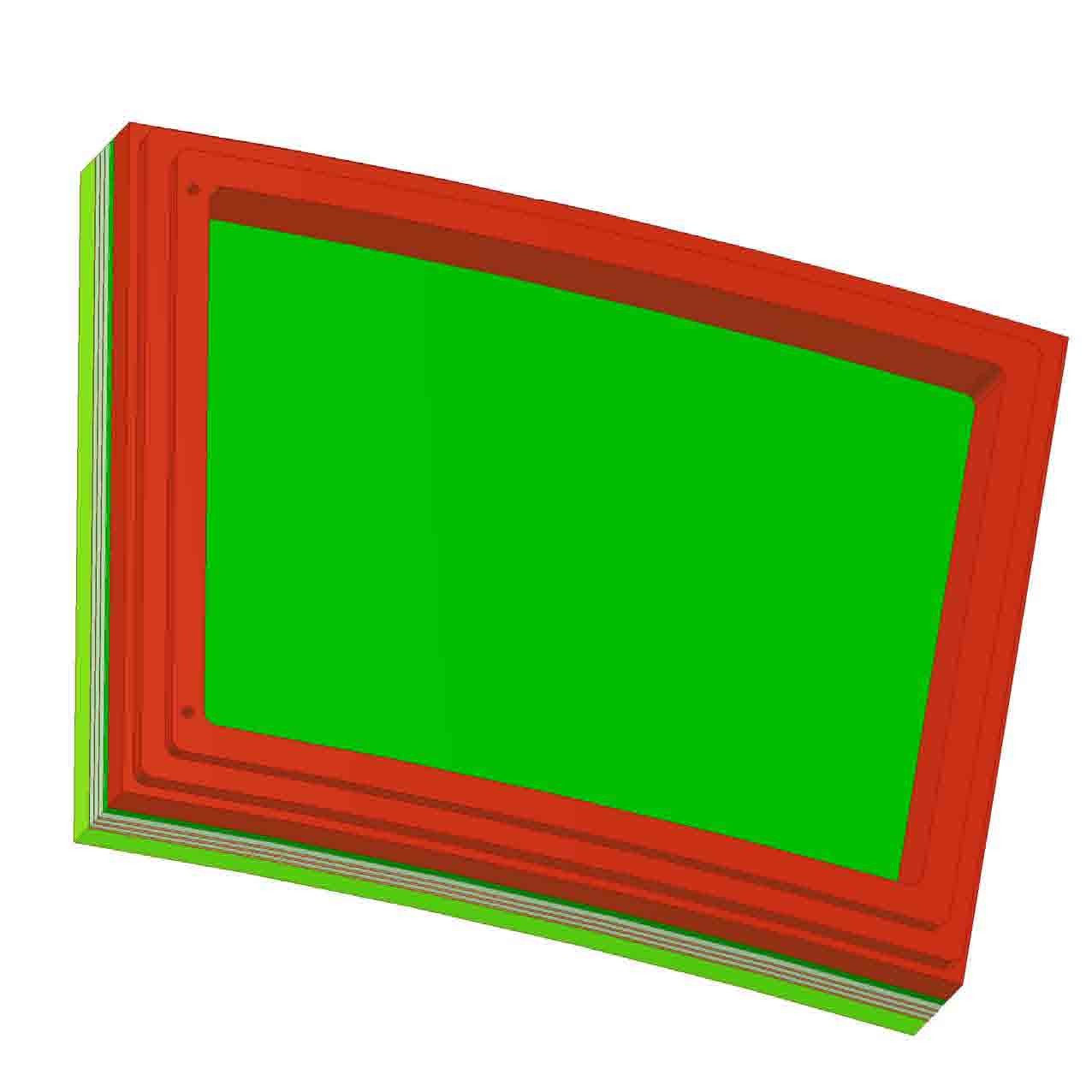
The first figure shows a model of a Micromegas (without gate) module.
The second figure shows a model of an endplate populated with Micromegas (without gate) modules. This can be compared to the 3GEM+Gate, 2007-04-17.
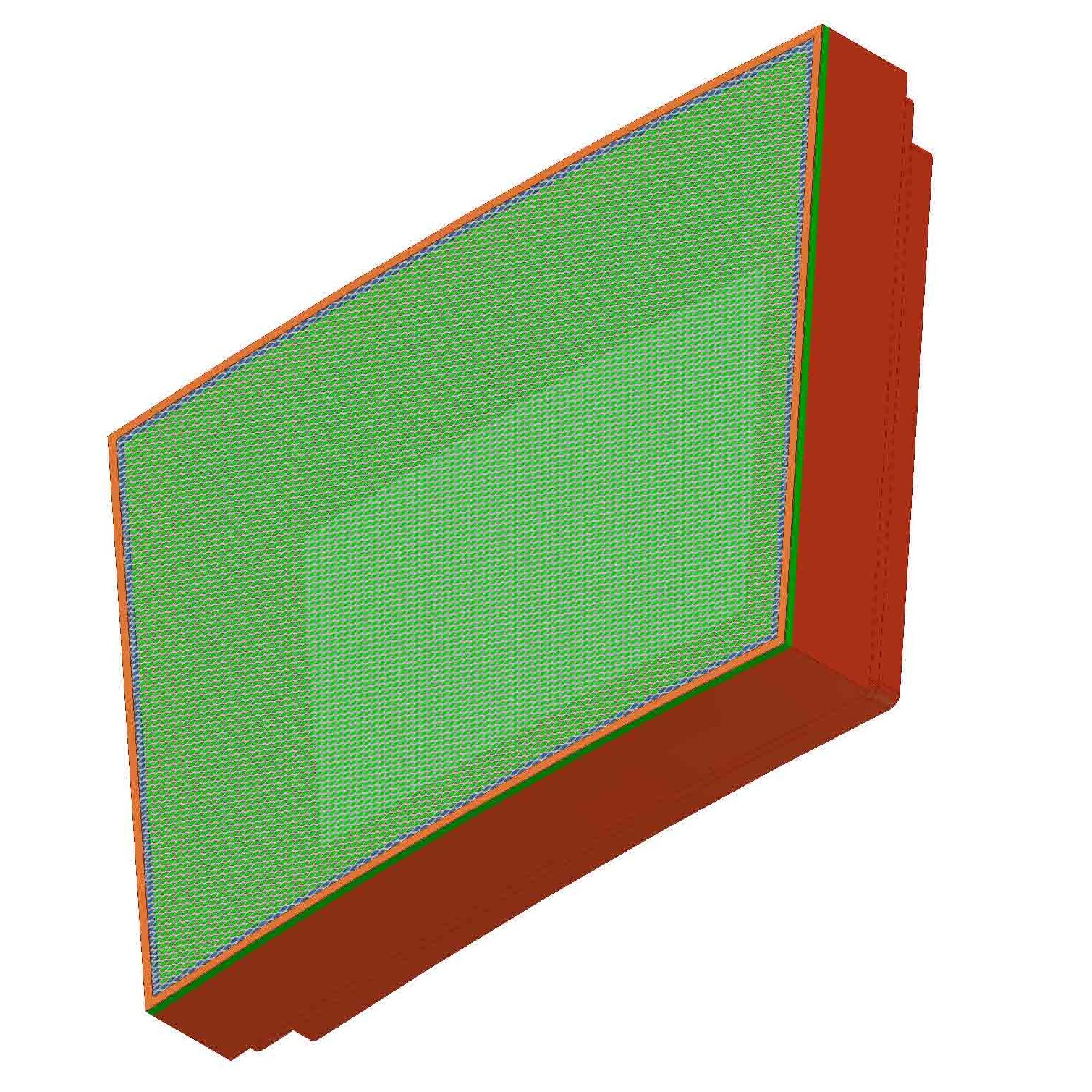
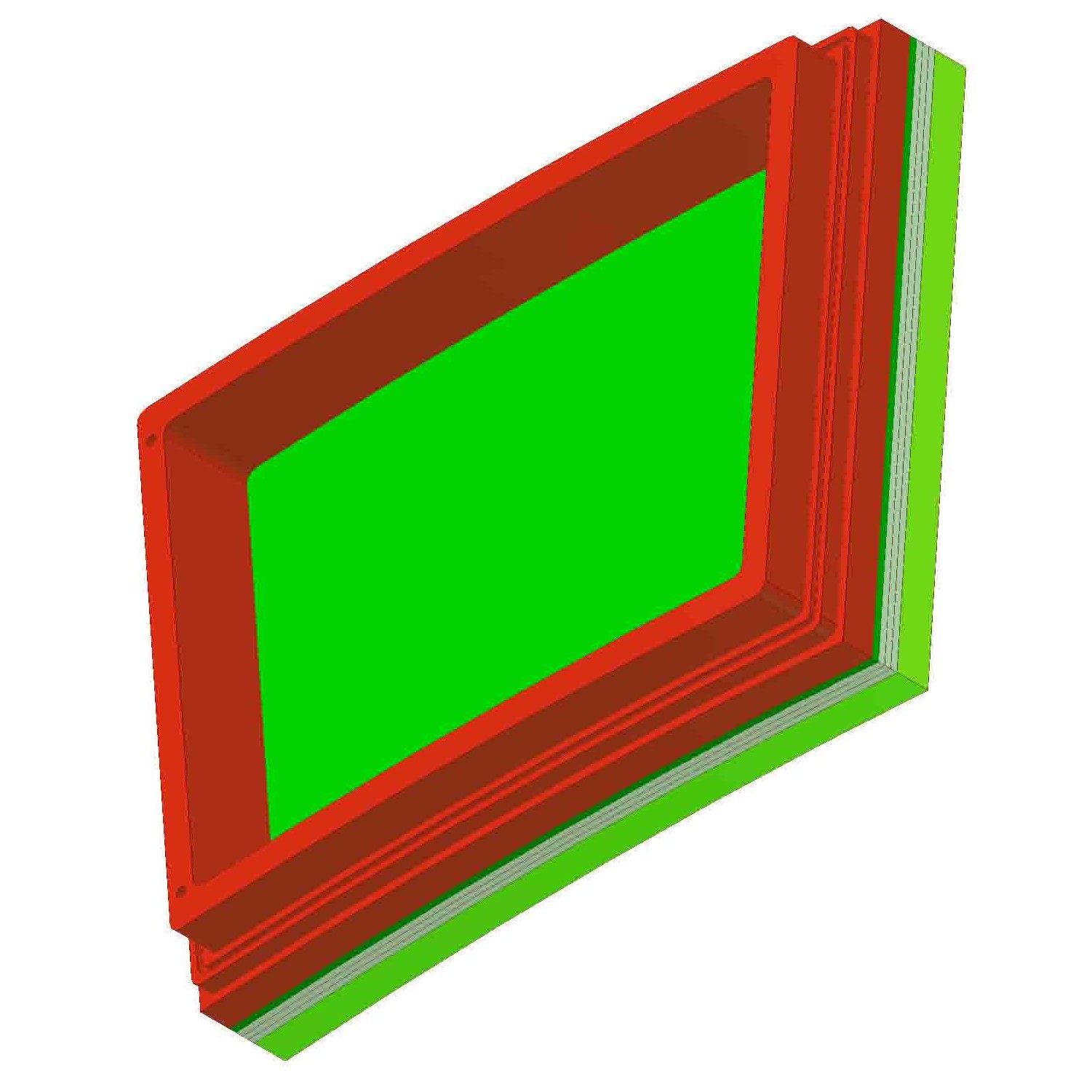
This shows the model and drawing (6080-103) of a "triple-GEM + Gate" module; it is an update of the version provided at DESY, 2007-06-04. Updates include changing the depth of one of the sections of the backframe (see pages 3 and 4 of the full drawing) to match the 28mm specification for the offset of the module face from the endplate. Another update is to include the o-ring groove. Note that this model provides 2mm for each of the GEM stages and for the pad board. It provides 10mm for the gate.
the model(jpg)
 (pdf)
....... and the full drawing (pdf)
(pdf)
....... and the full drawing (pdf)
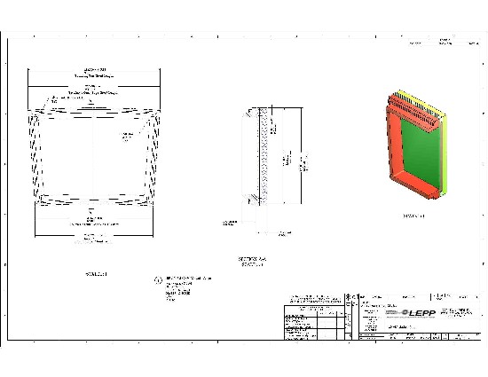
This shows the specification for the bounding box. It is actually page3 of the drawing above (6080-103); it has not changed since DESY, 2007-06-04. This is a "common center of curvature" design.
... the bounding box (pdf)
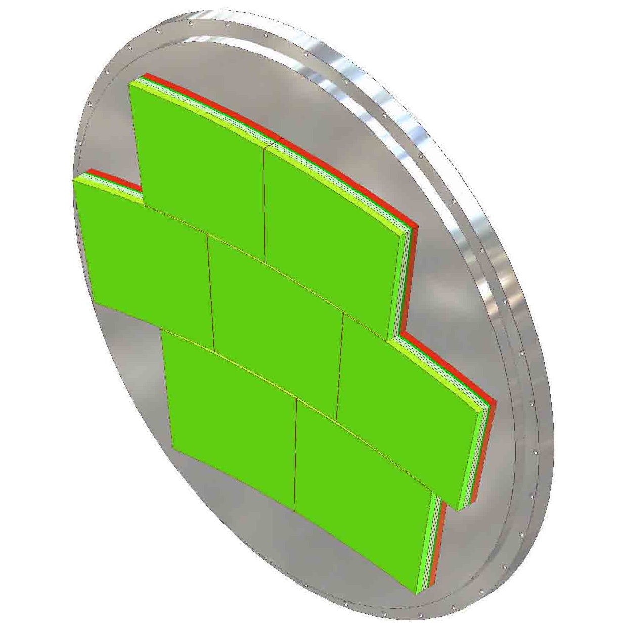
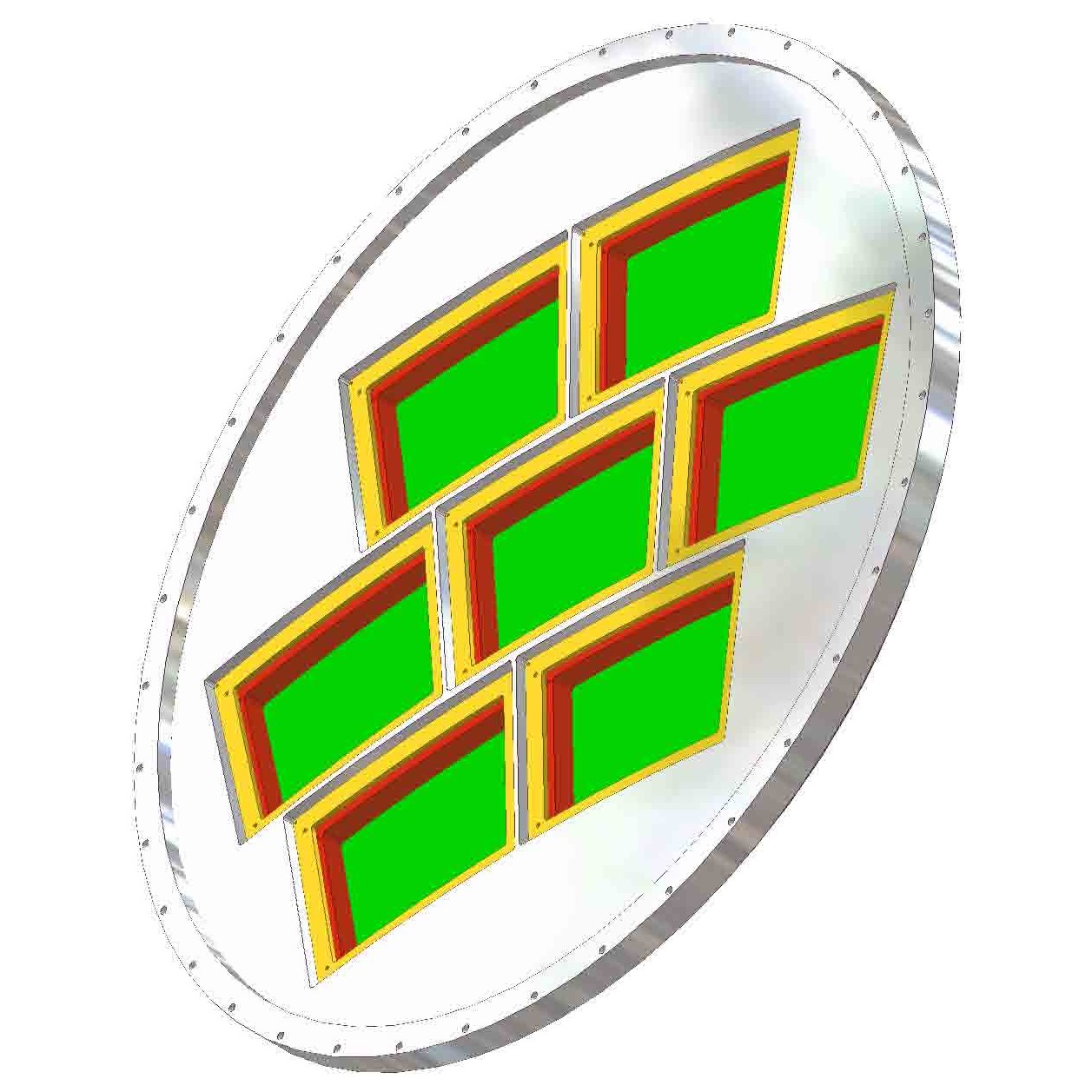
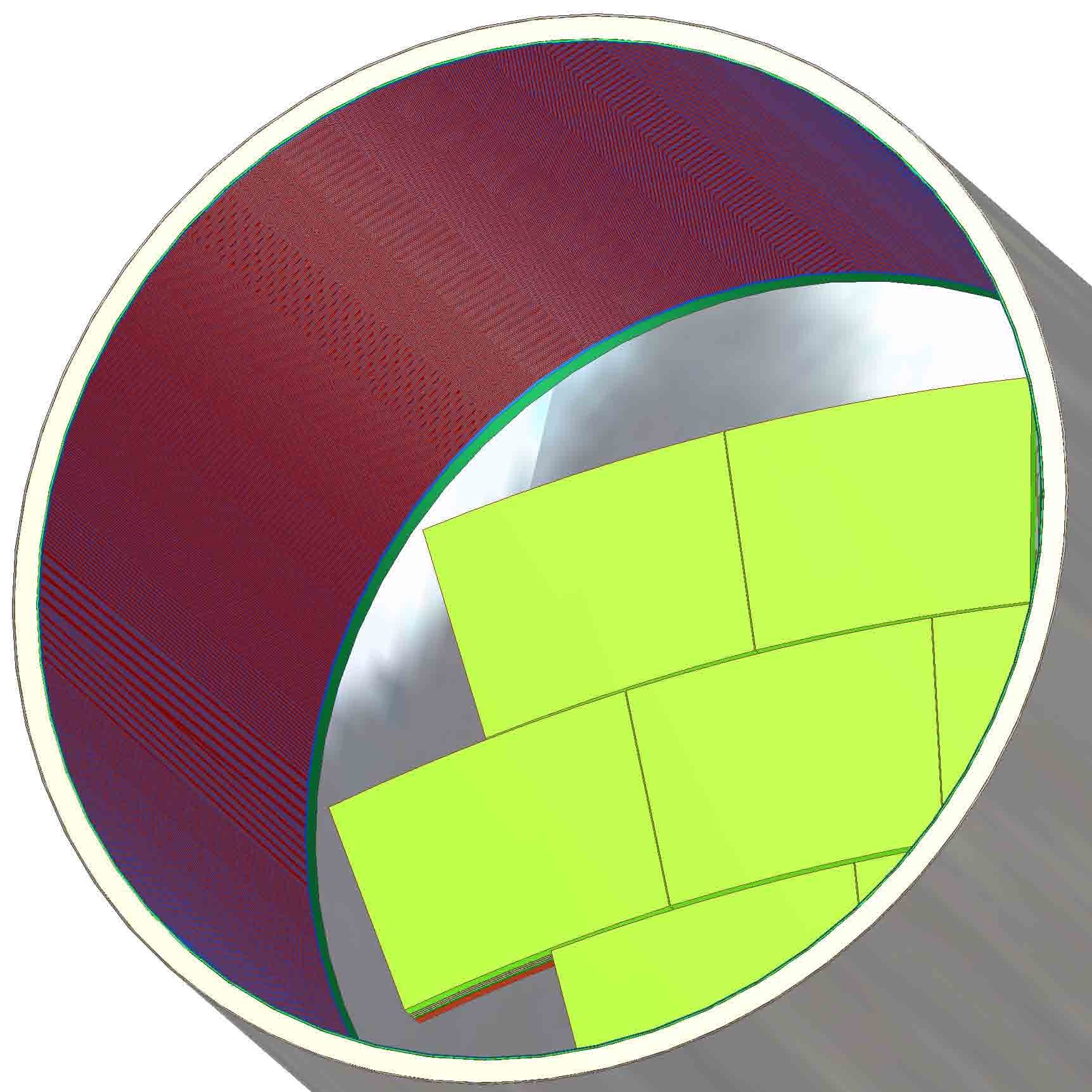
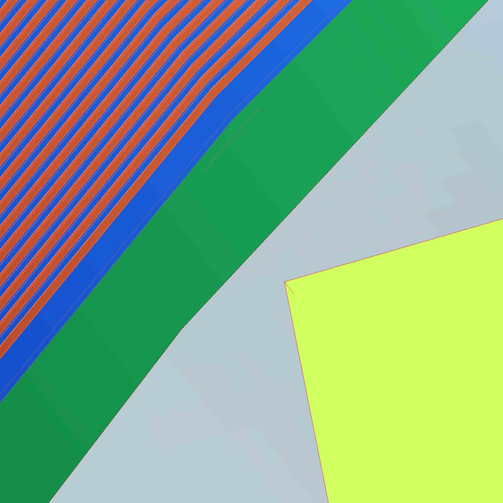
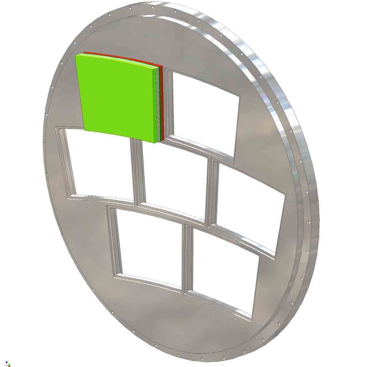
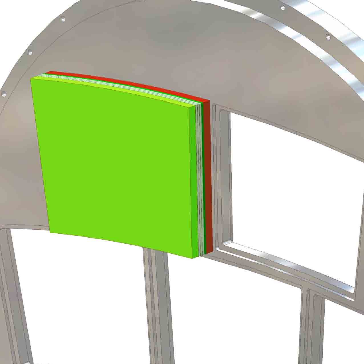
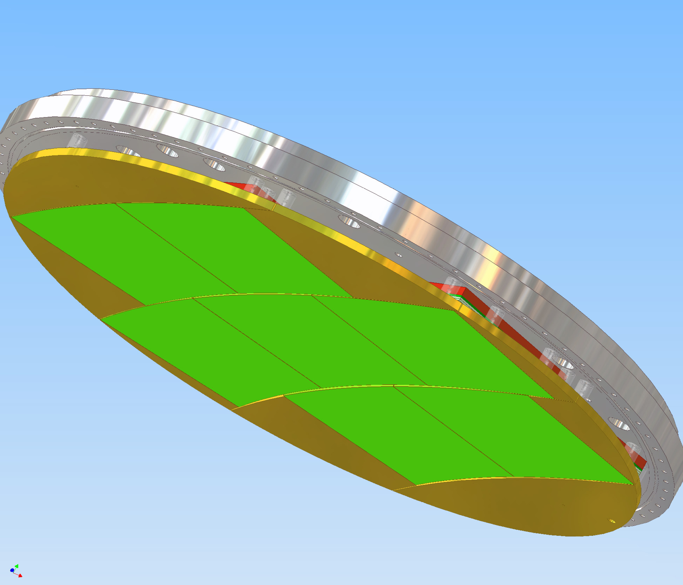
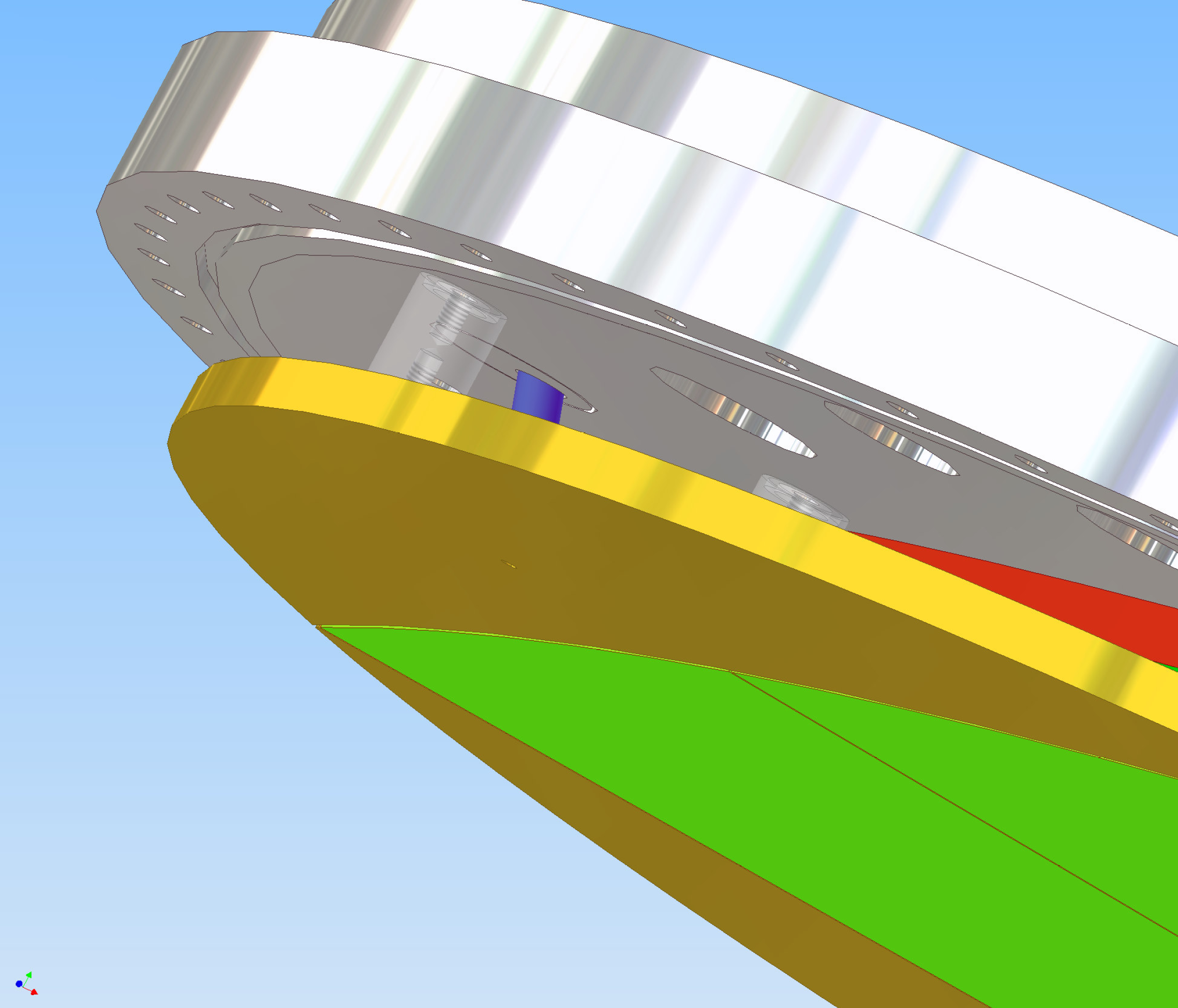
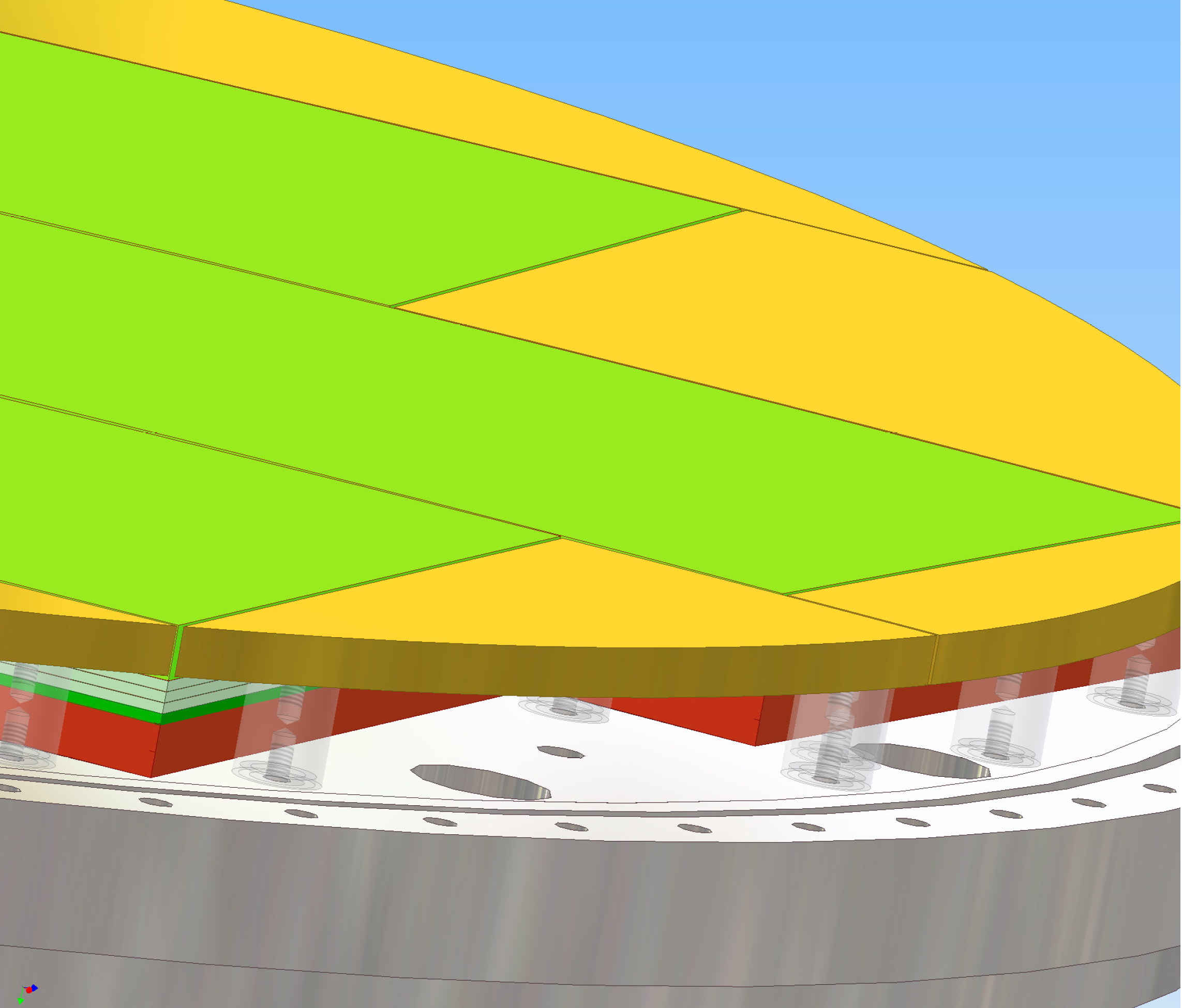
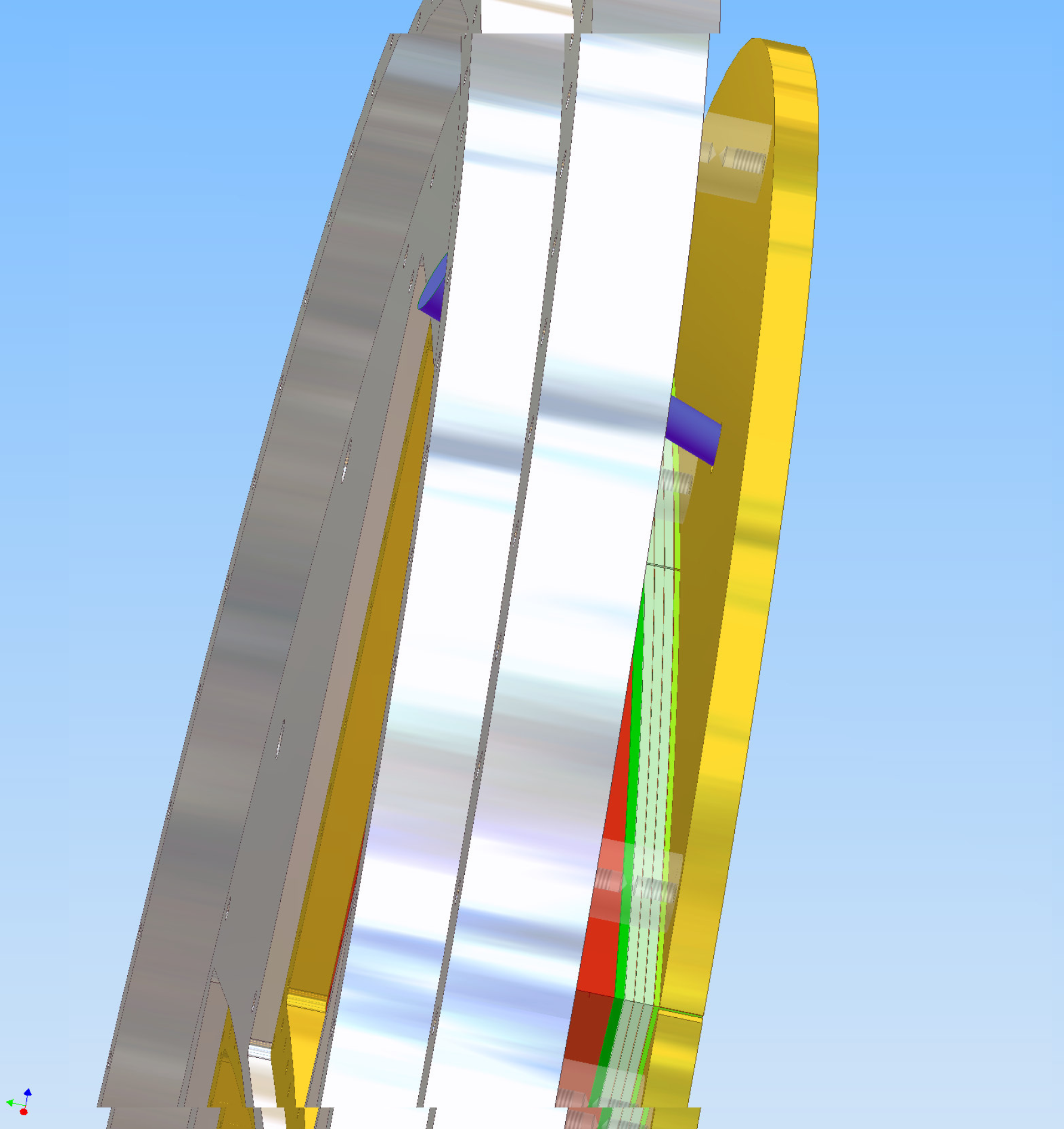
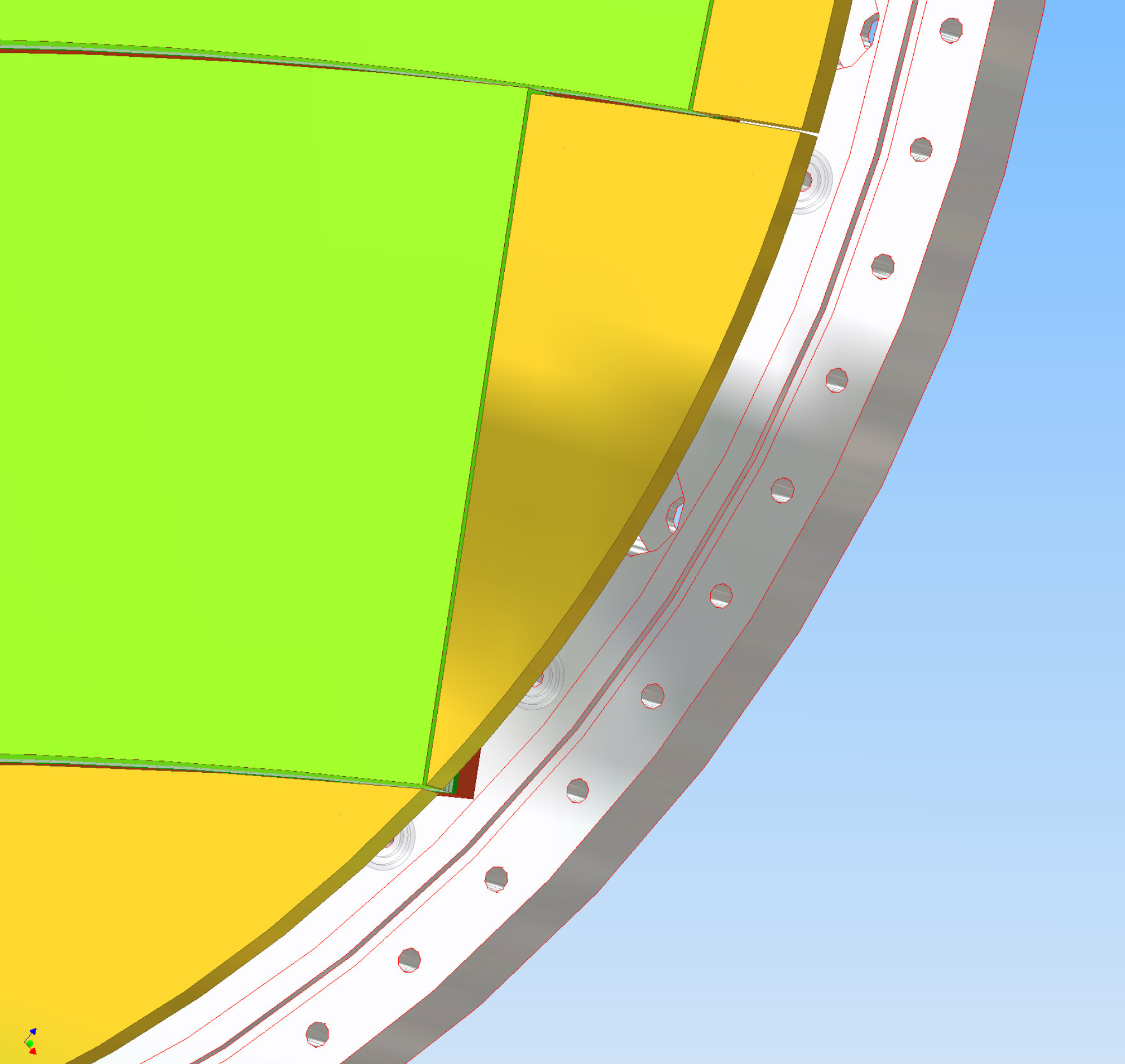
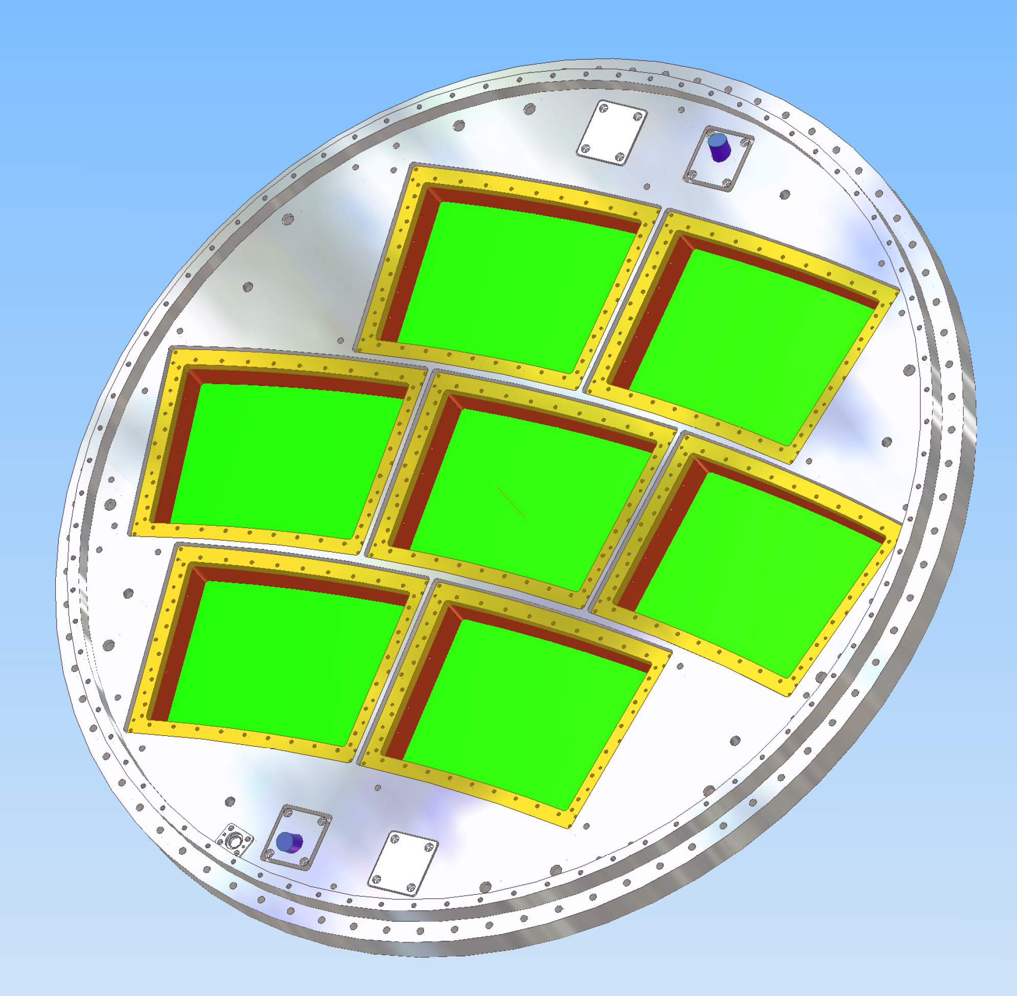
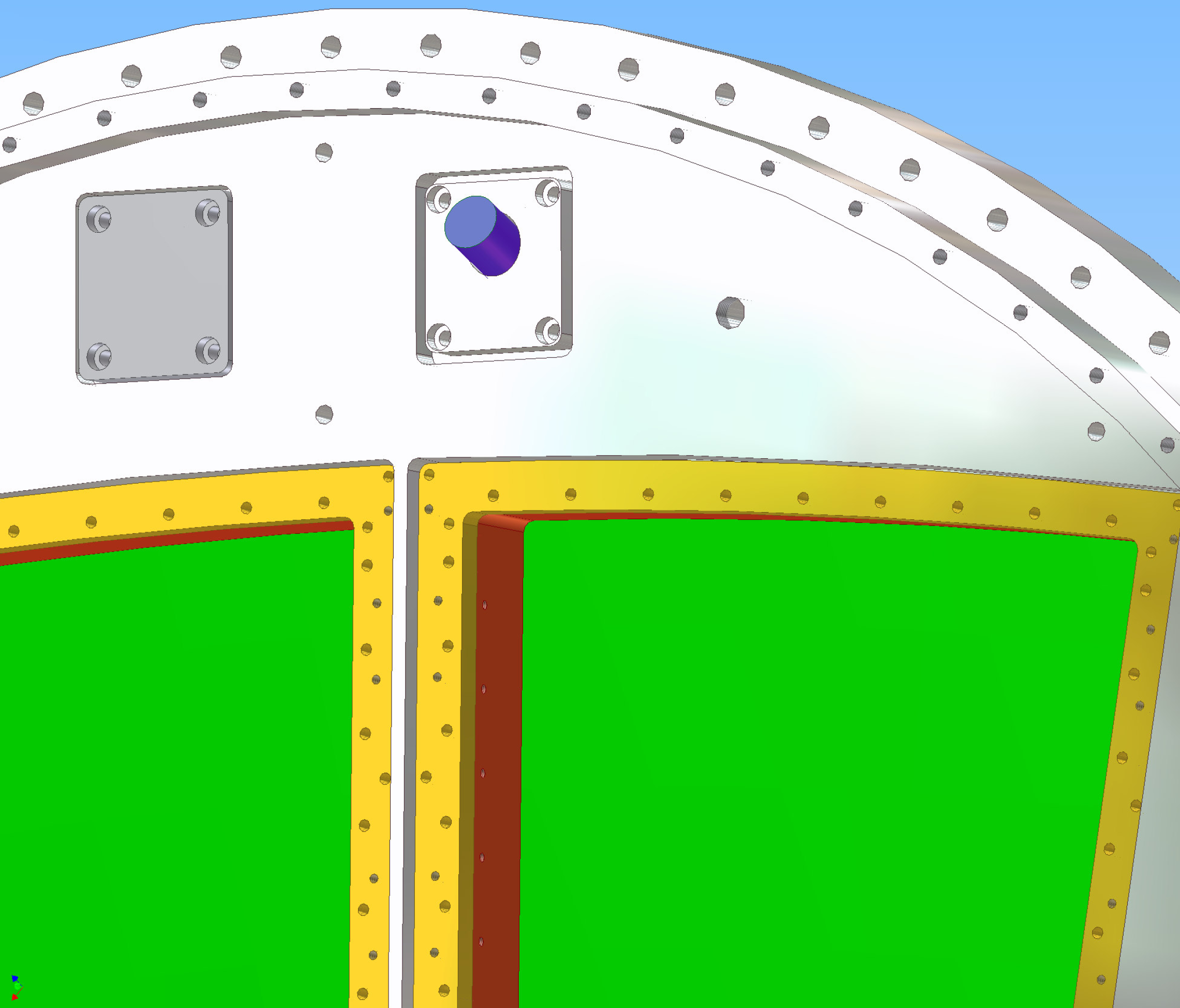
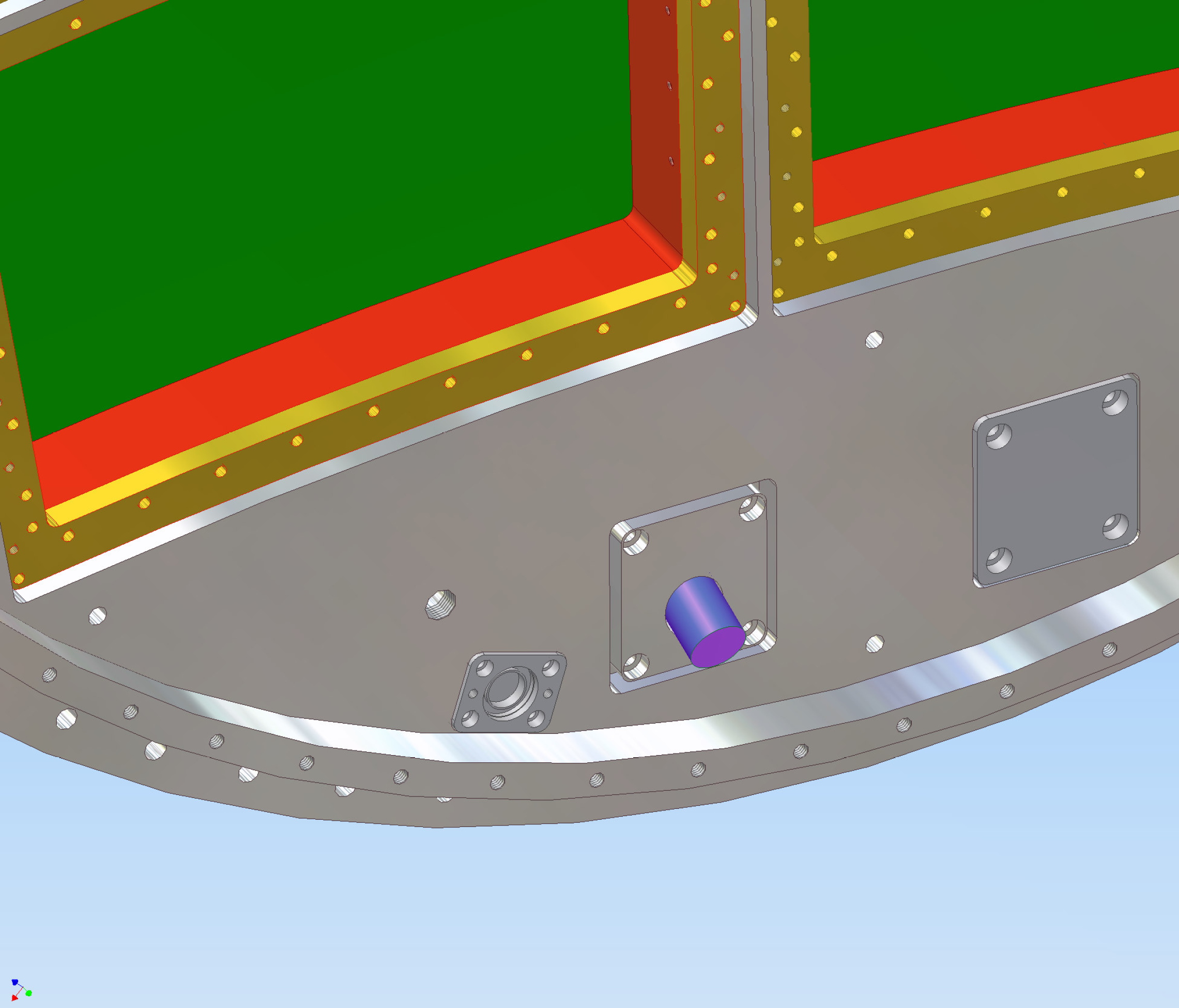
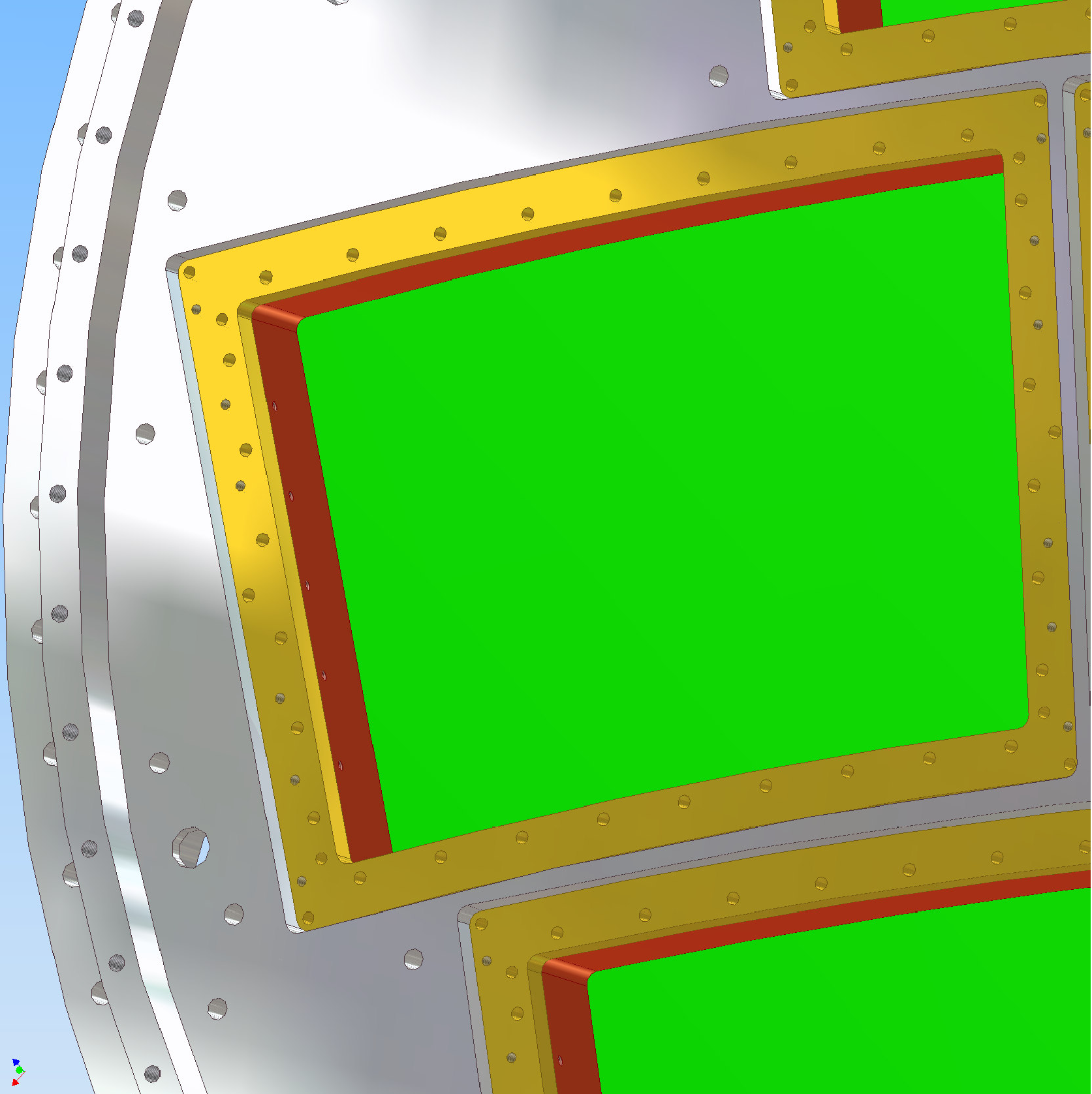
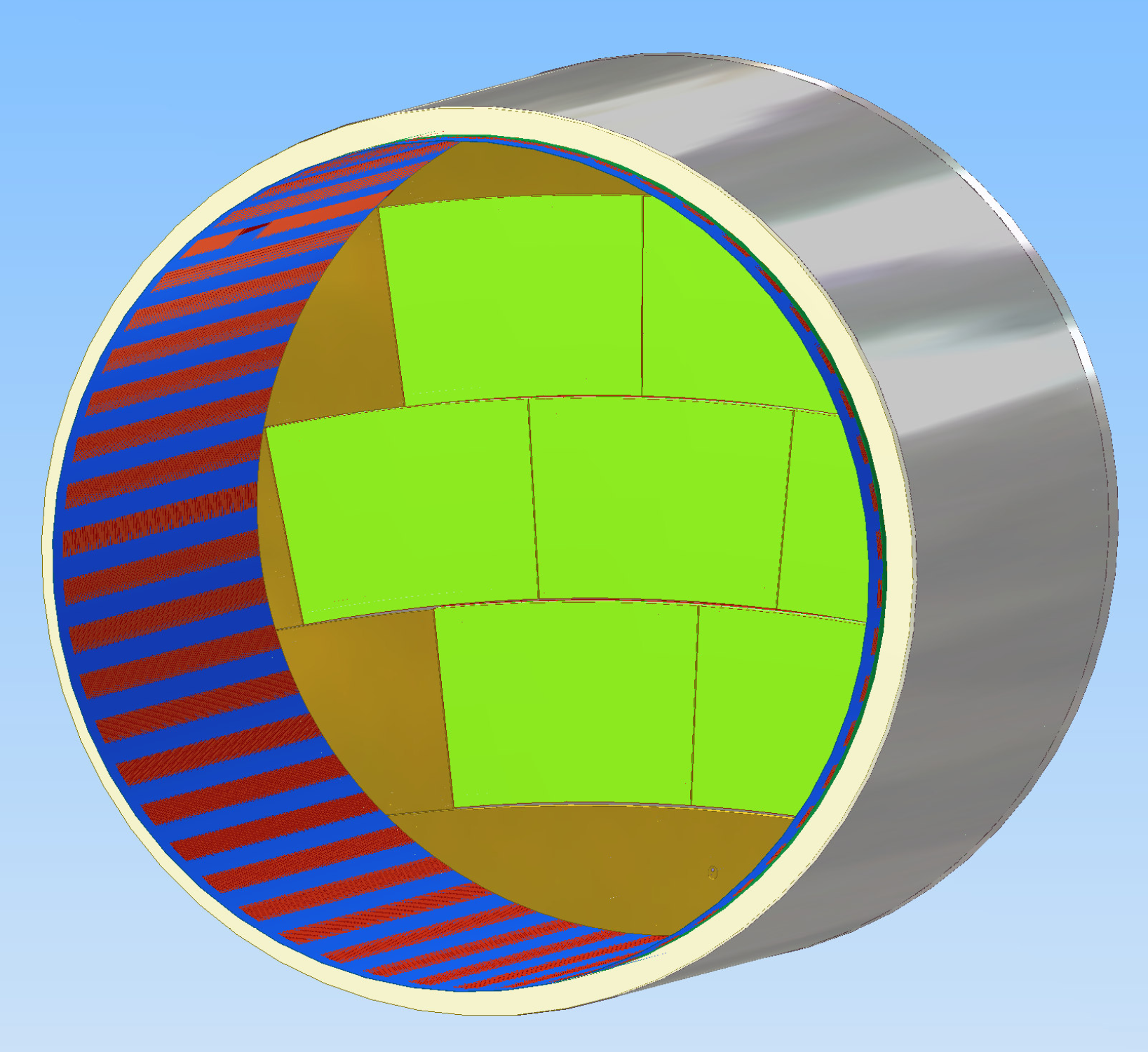
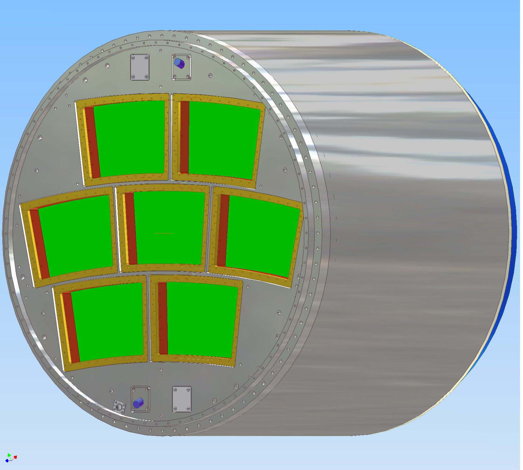
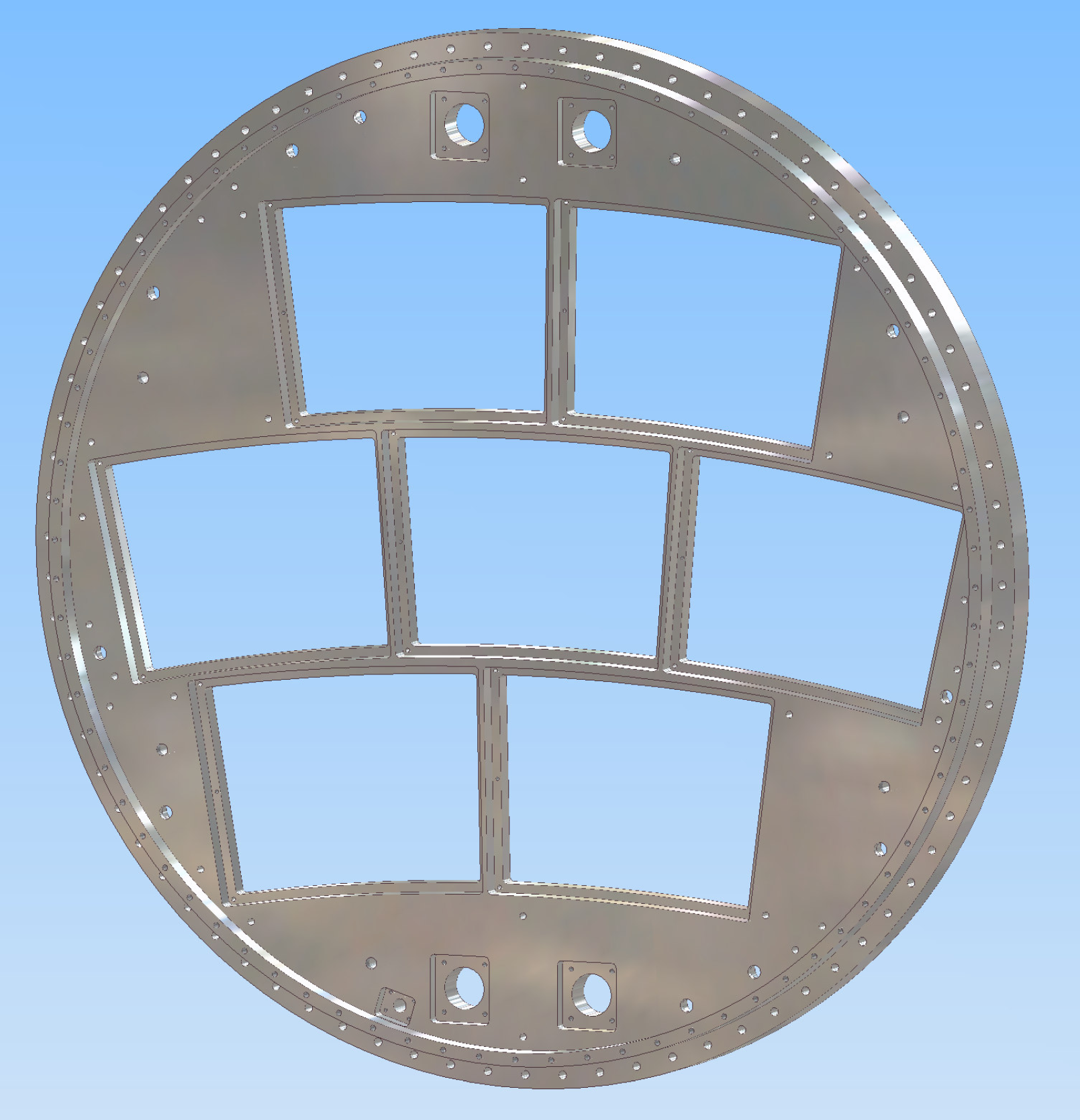
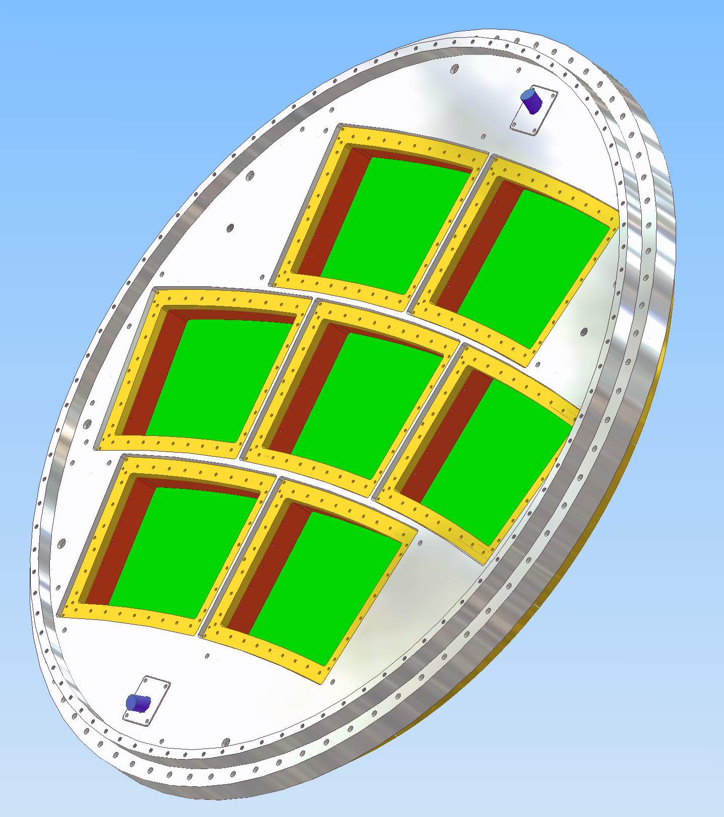
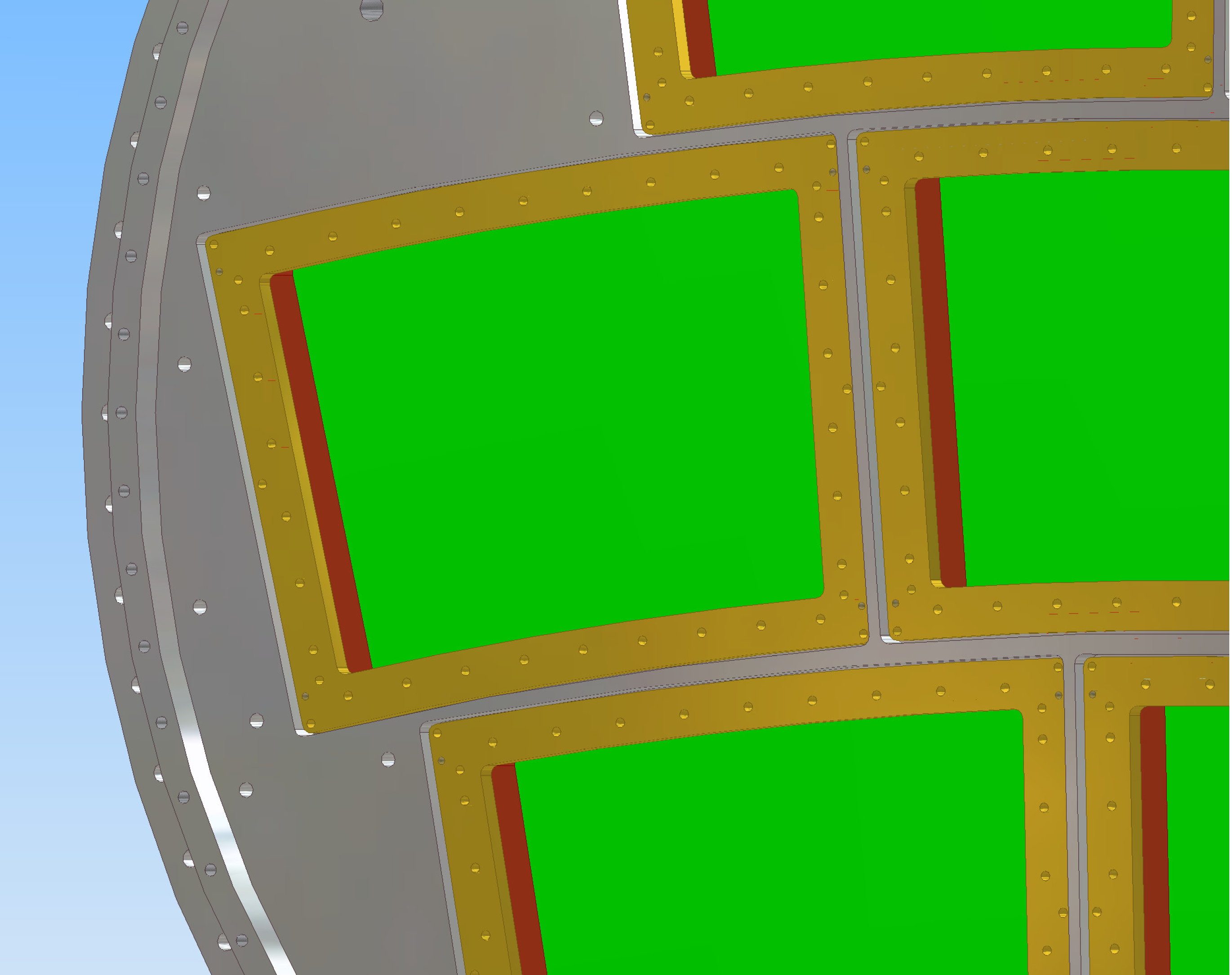
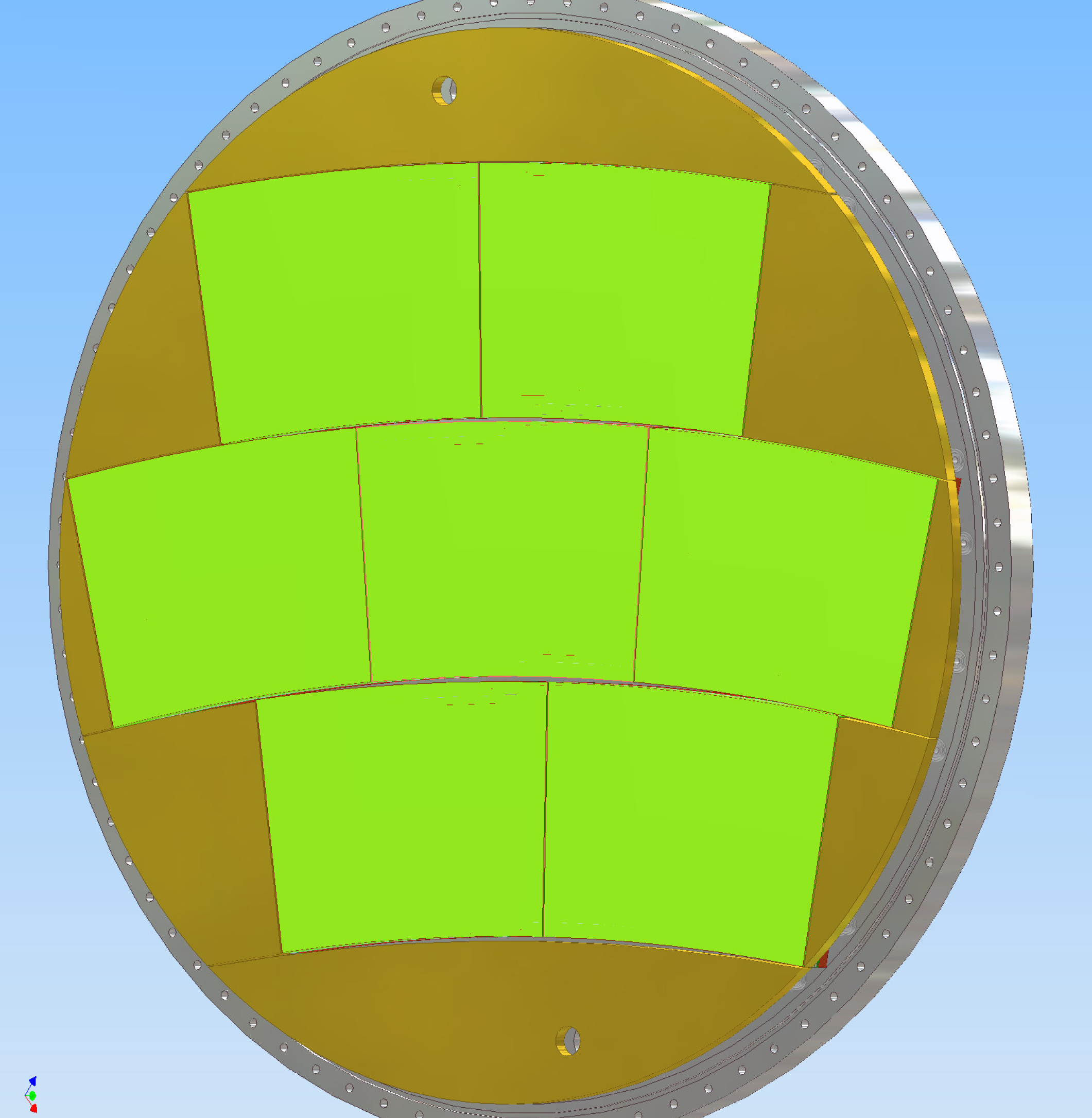
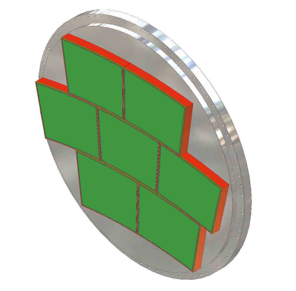
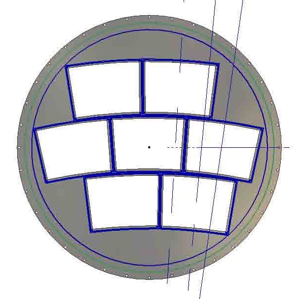
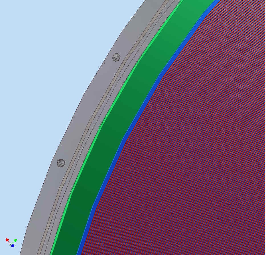
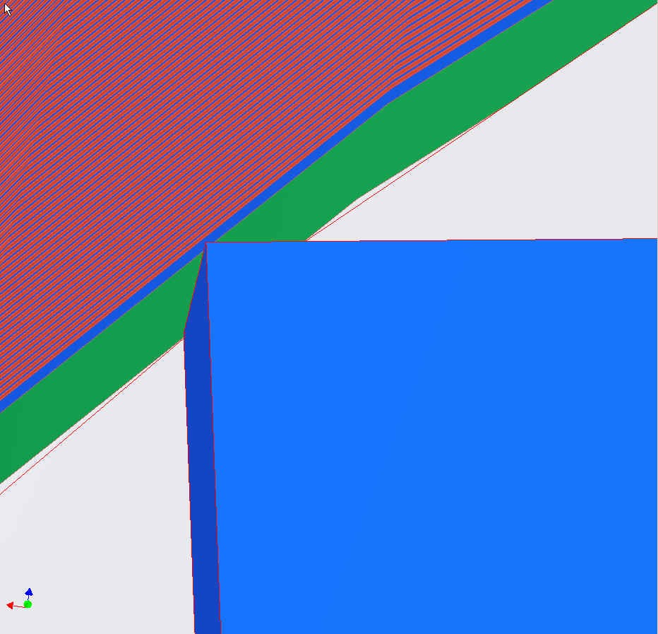
This shows the endplate, fully populated with 3GEM+G modules. The last figure in the row is a close-up of a corner of a module and the field cage. This corresponds to the geometry shown below, dated 2007-01-17.
Shown below are models of a "3GEM+Gate" module. This is using a bounding box with size: StraightWidth(TOP)=234mm, Height(CENTER)=170mm, StraightWidth(BOTTOM)=209.197mm, Area=37672mm^2 (9418 pads of area 4mm^2) as described 2007-03-20. If the height of the pad area is reduced by 10mm, at both the top and bottom, relative to the bounding box, the pad area is 33240mm^2 (8310 pads of area 4mm^2).
The support frame shown intrudes on each edge of the bounding box by 17mm. Thus the area remaining for connectors has WidthTop=200mm, WidthBottom=175mm, Height=136mm, Area=25500mm^2. The minimum area required for connectors is 12mm x 8mm per 32 channels, or 3mm^2 per channel. Thus, the available connector area can accomodate 8500 channels.
Or, the ratio of readout area to connector area is 33240/25500=1.304. Thus, with 3mm^2 per channel or connector area, the minimum pad size that can be accomodated is 3.91mm^2. Note that we also need to bring in biasing voltages, reducing the area available for signal connectors. Support frame dimensions are subject to change.
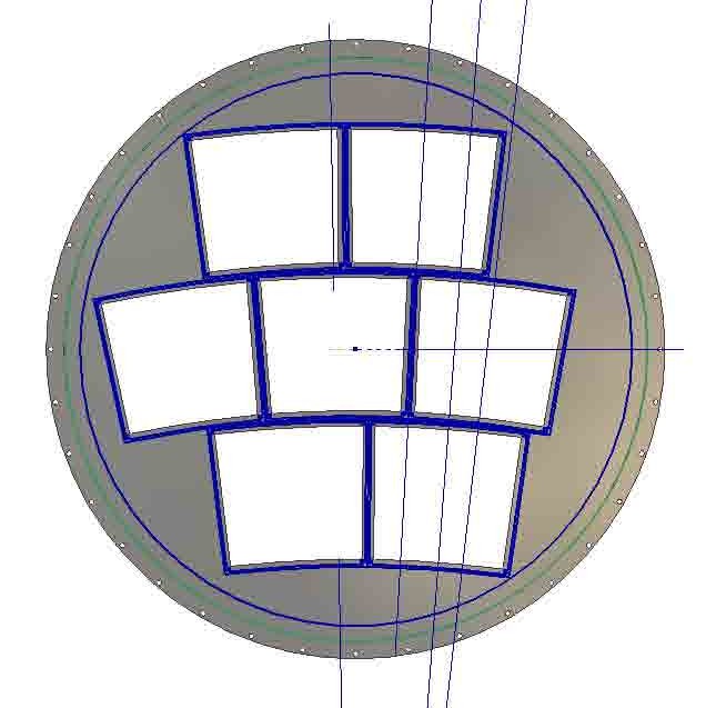
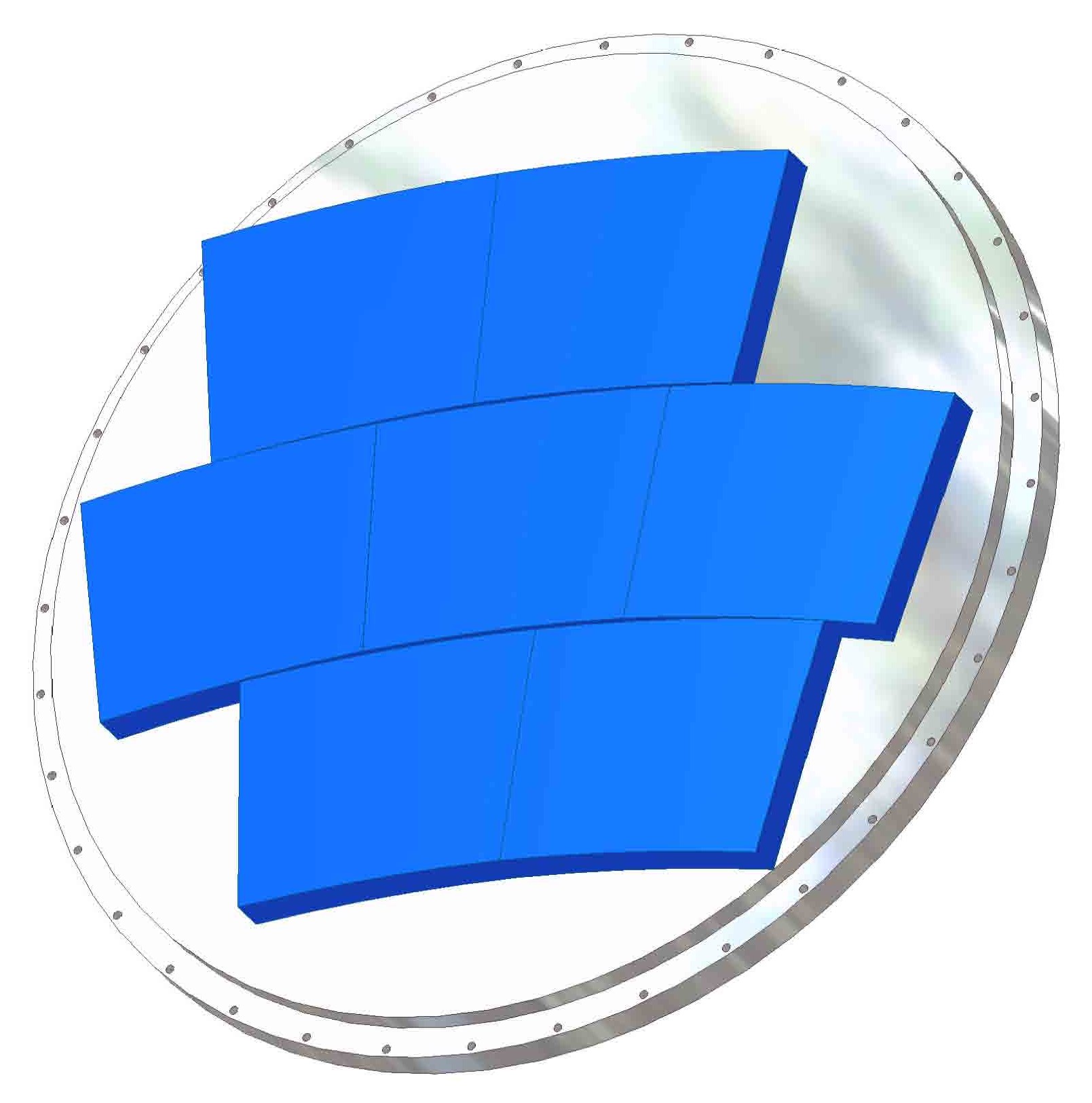
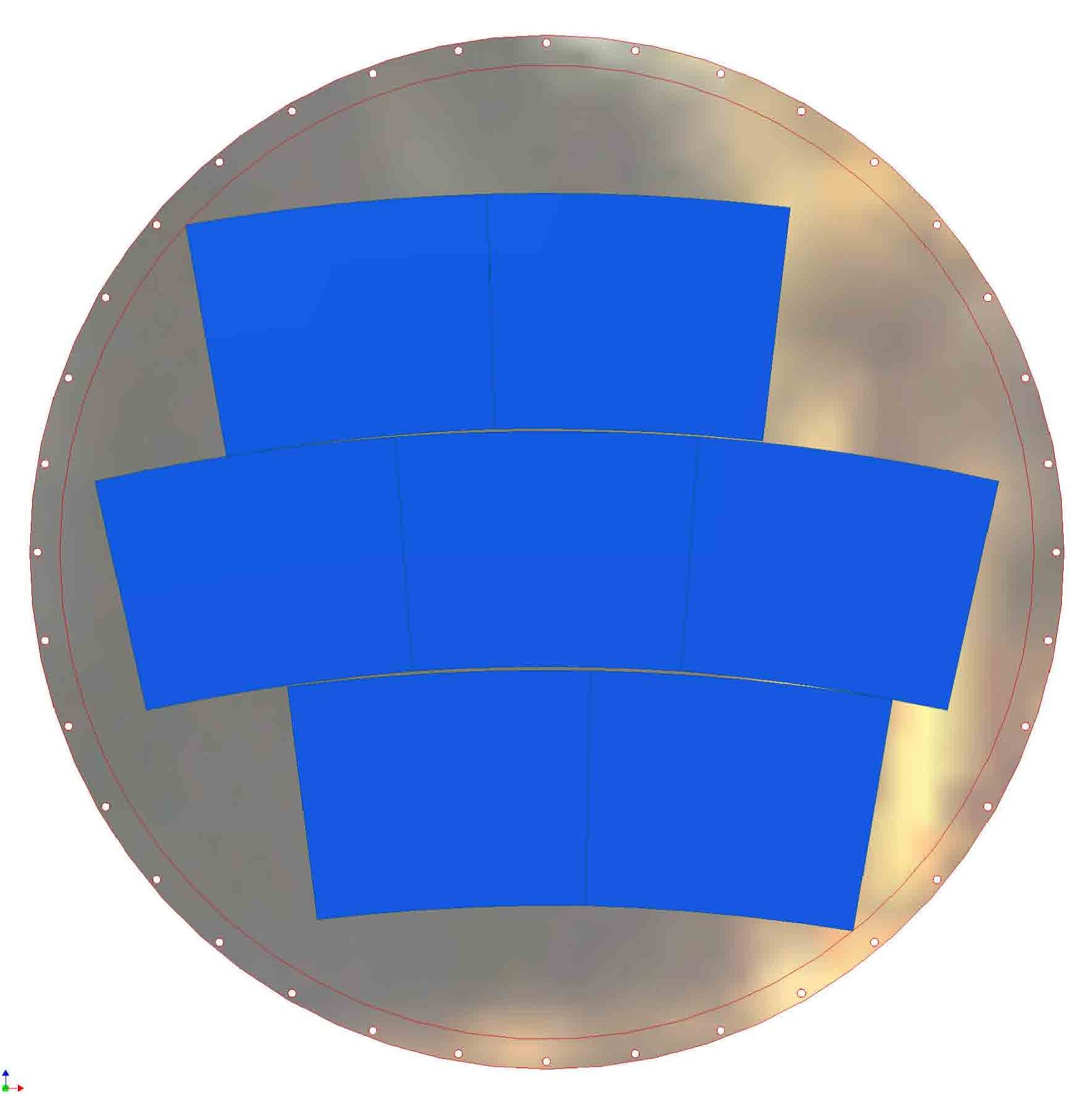
Shown below are models of a "3GEM+Gate" module mounted on the endplate. The endplate has "StayClear" radius=357mm and "StraightWidth(TOP)=234cm as shown on the left in the entry for 2007-03-20. (Bounding box positions are not fully optimized.) Shown on the outside-chamber view (3rd and 4rth figures) is a positioning and tightening bracket (shown in gold) with dowel holes into the endplate and the module frame(shown in red). (The Micromegas version, with a larger-offset frame, will be available after 2007-03-29. Models showning the assembly with the field cage will also be available soon after 2007-03-29)
Shown below are two examples of optimizations of the module size and location for the 7-module design. In both examples, the "StayClear" radius on the endplate is 357mm, due to a 400mm nominal field cage outer radius, 20mm field cage wall thickness, 3mm clearance (as shown below, 2007-01-17), and 20mm extra.
In both examples, the BoundingBox has OuterRadius=1600mm, InnerRadius=1600mm.
The center-of-curvatures are offset by the "Height(CENTER)" given below.
Left: StraightWidth(TOP)=234mm, Height(CENTER)=170mm, StraightWidth(BOTTOM)=209.197mm, Area=37672mm^2 (9418 pads of area 4mm^2). The OffsetFromCenterLine for the upper and lower rows (the amount by which a straight central track will miss the module edge) is 26mm.
Right: StraightWidth(TOP)=209mm, Height(CENTER)=190mm, StraightWidth(BOTTOM)=184.228mm, area=37357mm^2. The OffsetFromCenterLine is 15mm. The more "square" design on the right has slightly less area, and would have a further small reduction in area to increase the OffsetFromCenterLine to 20mm. However, there would be less area lost to upper and lower support frames.
Note: the module is smaller than the bounding box.
The module is to have 0.5mm clearance from the bounding box on all edges.
Another note: as stated above, these dimensions were created using a "StayClear" radius of 357mm. On 2007-04-25, we agreed to a "StayClear" radius of 362mm.
On 2007-05-09, we agreed to use the 2007-03-20("Left") dimensions.
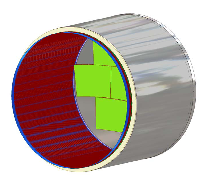
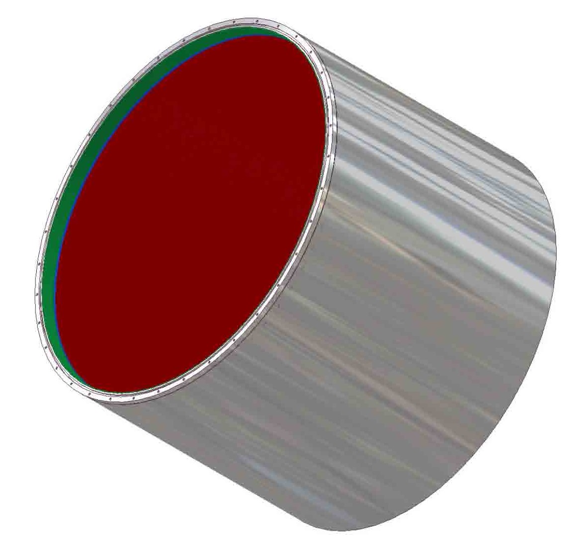
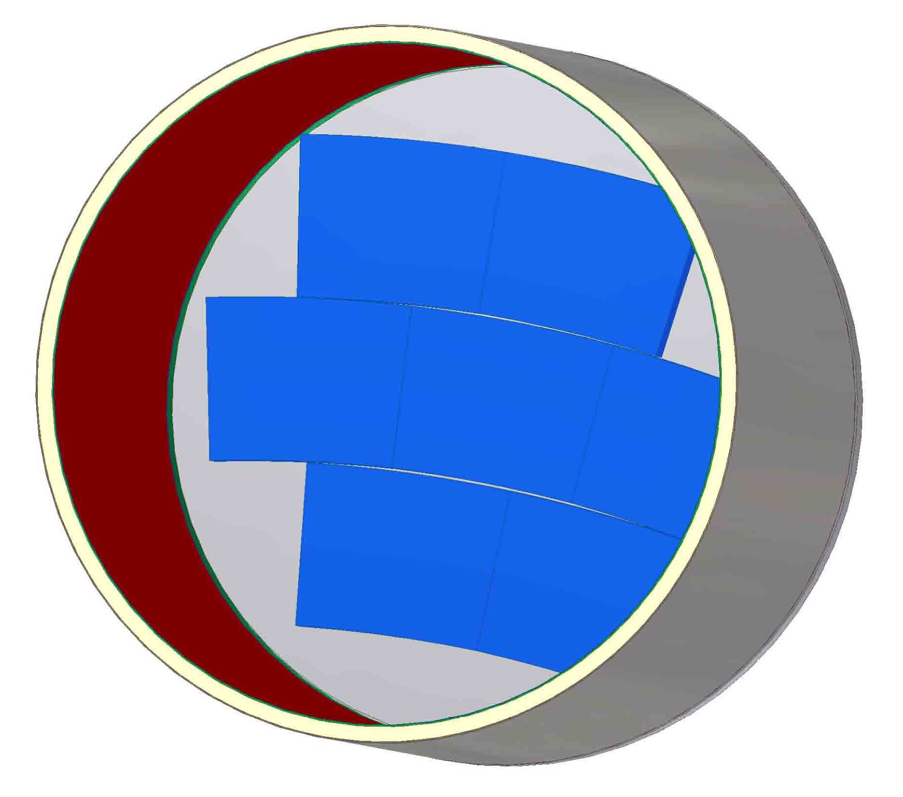
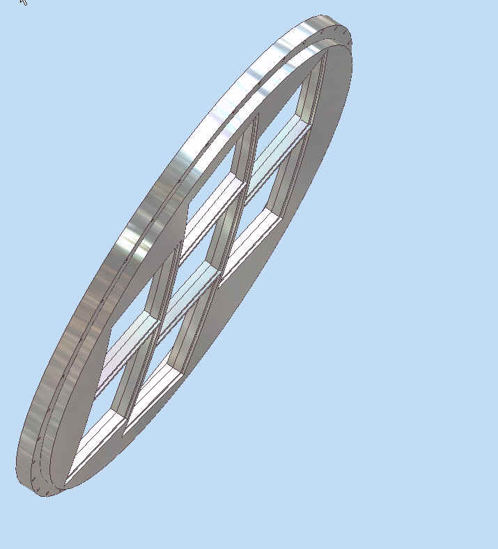
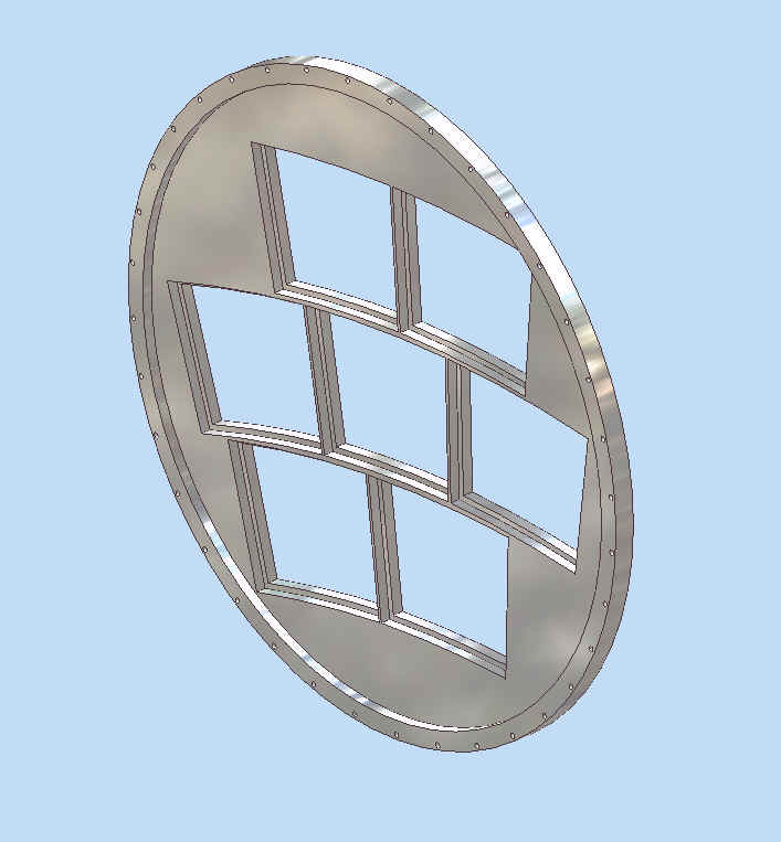
This shows a field cage with 40cm outer radius and 2cm wall thickness. It is an attempt to follow the drawing labeled "04.12.06" provided by Peter Schade. However, the offset of the first field band is as specified below (17-January-2007).
This is an optimization of the 7-module design, with the 2mm thick field cage, with a 377mm "StayClear" radius. This is done in "adaptivity" approach that has been discarded in March 2007. The blue things are the bounding boxes, not any particular readout module.
These models are made with the new drawing structure in which the BoundingBox is defined as a part that is only a parameter list. Each physical part model is then an assembly of the BoundingBox and a model specific to that physical part. The "StayClear" is 2cm inside the available "canvas" given by a field cage with 40cm outer radius and 2cm thickness.
These are modeled using "adaptivity". In this case, the bounding box is a part. The "adaptivity" approach was discarded. It allowed definition of the endplate openings from a single sketch. However, it was difficult to define the readout module components mated to the opening.
 (purdue)