This page contains details of some of the projects that I've worked on. You can scroll through or navigate to individual projects using the links here:
- Cavity Testing
- ANSYS Simulation and Cryomodule Design
- Designing and Building a T-map System
- Designing and Building a Slow Cool System
- Designing and Building a Tc System
- Designing and Building a Nb3Sn Coating System
- Commissioning Nb3Sn Coating System
- Nb3Sn Cavity Results
- HOM Measurements and Cryomodule Assembly
- Cryomodule Testing and LLRF
- Superconductivity Theory
- Instrument Communication and Process Automation
- Microwave Equipment
- Undergraduate Projects
Cavity Testing
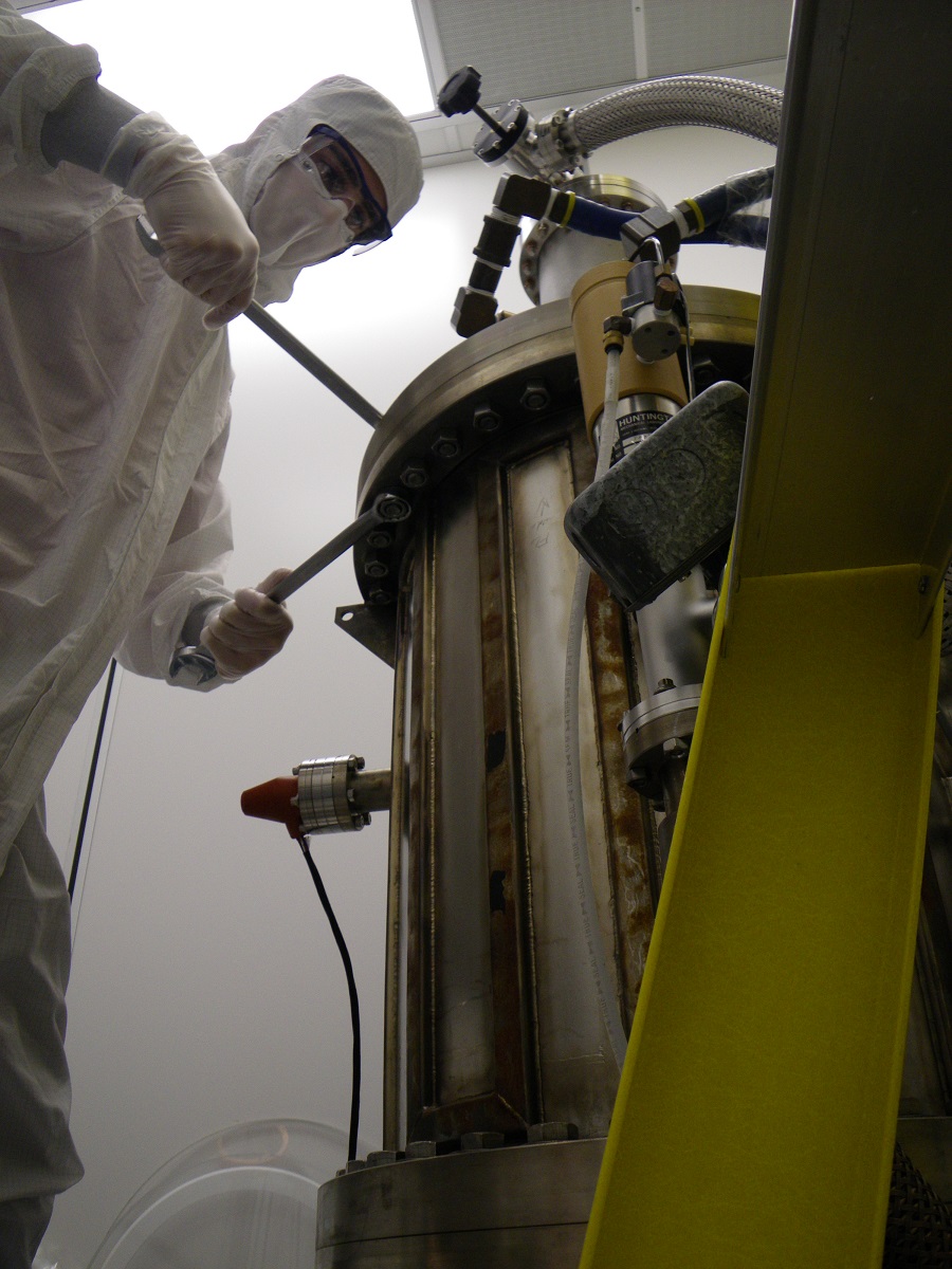
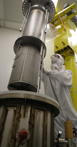
In my time at Cornell, I've performed dozens of vertical tests of SRF cavities. This involves preparing a cavity in the clean room, cooling it to ~2 K, and then evaluating the performance of the cavity, primarily by measuring the quality factor (which determines how much power the cavity would dissipate in a helium bath) as a function of accelerating field. We use a phase-locked loop to drive the cavity at its resonant frequency, as when it is superconducting, its bandwidth drops to as low as ~0.01 Hz. In order to run experiments independently, I learned to operate the cryogenic system myself (helium transfers, recovery, pumping, and temperature control above 4.2 K) and have done so for the majority of my tests. I also dress the cavity with diagnostic instruments before testing, like temperature sensors, helium level sticks, oscillating superleak transducers, fluxgate magnetometers, as well as heaters and power cables, and I make sure everything works. Finally, during the test, I am responsible for the measurements and data acquisition.
Related publications: SRF11
ANSYS Simulation and Cryomodule Design
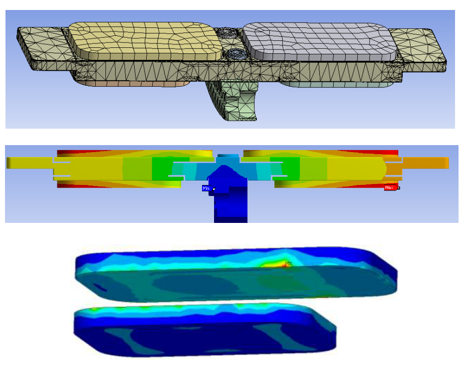
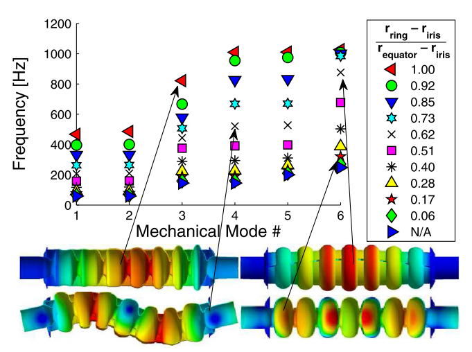
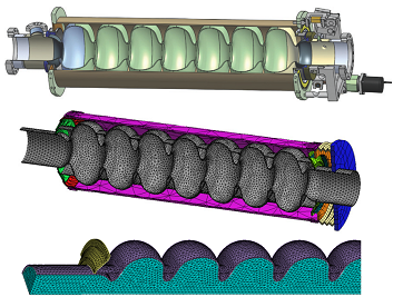
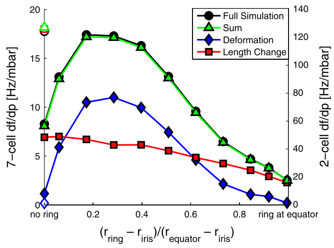
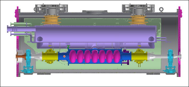
Over my Ph.D. studies, I've become highly skilled with the engineering simulation software ANSYS. It is a very useful environment for predicting, for example, the stress in a component when a load is applied or the temperature distribution in a cavity with thermal intercepts and RF heat loads. In the latter case, one can estimate the heat load to each intercept and make sure that the heat sinking of RF pickup antennas is sufficient. The hard part for me was learning how to integrate structural simulations with RF simulations. By transferring data from the modern ANSYS Workbench to ANSYS Classic (this transfer is key to achieving good meshes with CAD-built models), I can predict df/dp and Lorentz force detuning for a cavity. My ANSYS simulations were used to plan cuts to relieve thermal expansion stress in the Cornell ERL injector HOM absorber tiles and to optimize the Cornell ERL main linac cavity assembly. With the main linac cavity, I performed a detailed study of the effects of stiffening ring placement, tuner choice, and assembly stiffness.
Related publications: Talk at HOM10, publication in Phys Rev: ST-AB, IPAC12, SRF11 (1) (2), IPAC10
Designing and Building a T-map System
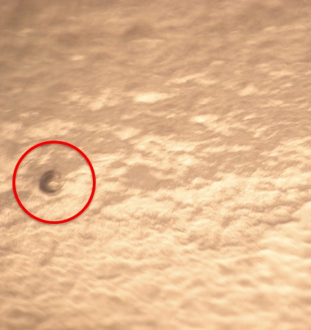
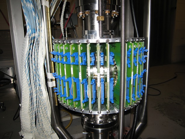
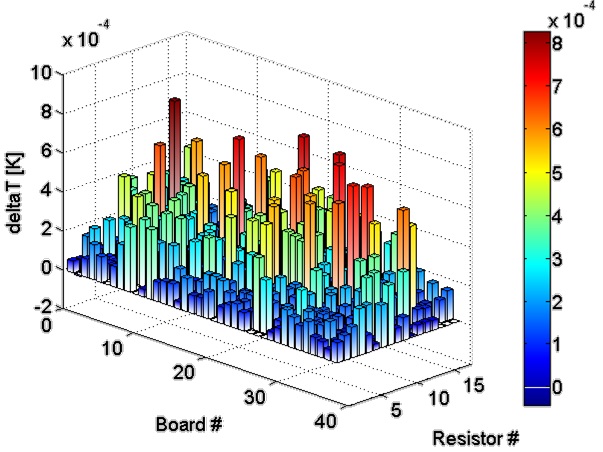
In 2011, we decided that there was need for a temperature mapping system (T-map) for R&D cavities. A T-map consists of an array of hundreds of temperature sensors arranged over the surface of the cavity so that the distribution of heating can be localized to about 1 cm^2. This valuable information is used to diagnose performance limiting mechanisms. For example, in the case of a localized defect, after testing, the optical inspection telescope can be used in the region of maximum heating to locate the defect and conclusively link it to poor RF performance.
An obsolete T-map existed already, which had been used to test a cavity shape that is no longer in use. It could not be used to test cavities with standard TeSLA or Cornell ERL shapes. However, we were able to recover from it hundreds of Allen Bradley carbon resistors used as RTDs, which are pressed against the cavity surface with "pogo sticks." We were also able to reuse the multiplexing data acquisition boxes and connecting cables.
Working with the drafting department and the electronics shop, I designed printed circuit boards to properly hold the temperature sensors against the cavity and connect to the resistance-measuring circuit, as well as aluminum plates to hold the boards securely against the cavity. We hired a Cornell undergraduate, who I trained to solder the resistors to the boards and test the connections. Finally, I wrote a MATLAB program to interface with the multiplexers, calibrate and read out the T-map, and plot temperature rises over the surface of the cavity. The T-map has since become a workhorse of Cornell's R&D program.
Related publications: IPAC12 (1) (2)
Designing and Building a Slow Cool System
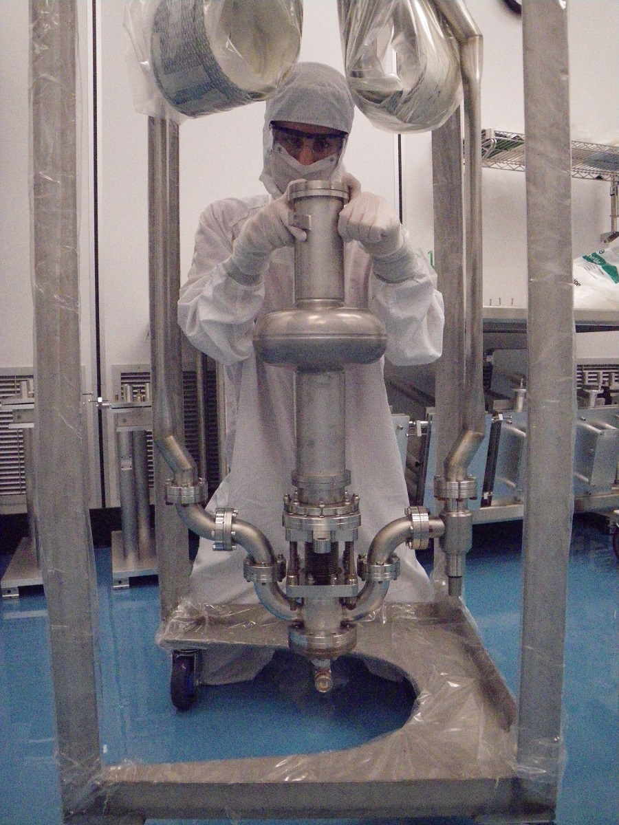
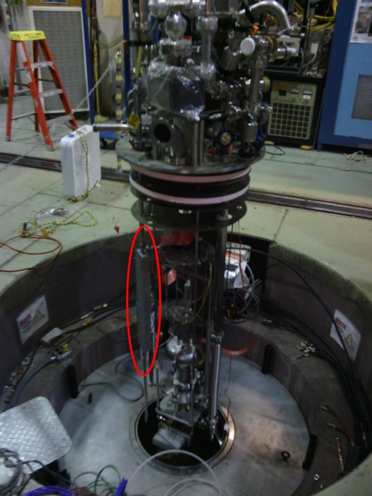
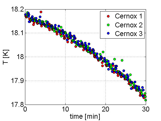
In the literature, previous experimenters have reported poor performances in Nb3Sn cavities that were cooled below their critical temperatures in the standard, fast way. They found that if they cooled their cavities very slowly, at ~10 K/hour, they could avoid Q-degradation that they attributed to thermocurrents between the Nb and Nb3Sn layers. I knew that by the time I produced a cavity, I would need to have made an apparatus to cool down the cavity extremely slowly and uniformly, so that I could be confident that any poor performance was not caused by this thermocurrent effect. I thought of several systems, such as a series of heaters over the surface of the cavity, a heater below the insert that would boil the liquid helium as it entered, or a bladder to isolate the cavity from the flow of cold helium. I decided that the only way to make sure that I could uniformly cool down the cavity in a controlled way was to admit helium gas with a chosen temperature to the dewar, so that the temperature could fall roughly isothermally. With this idea, I designed and built a system that would throttle liquid helium flow to a manageable level, then boil it and warm it using several stages of heaters. The system as designed exceeded its performance goal, providing a wide range of cooling rates even below 10 K/hour. The tool I developed has been essential for my Nb3Sn cavity tests. It has also been very important for tests run by fellow grad student Dan Gonella, in which he measures the effect of cooldown rate on nitrogen-doped cavities in the presence of external magnetic fields.
Designing and Building a Tc System
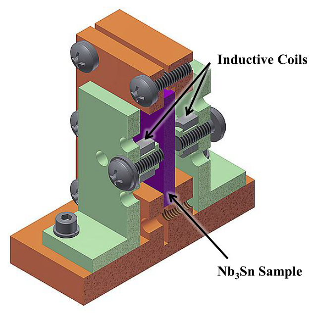
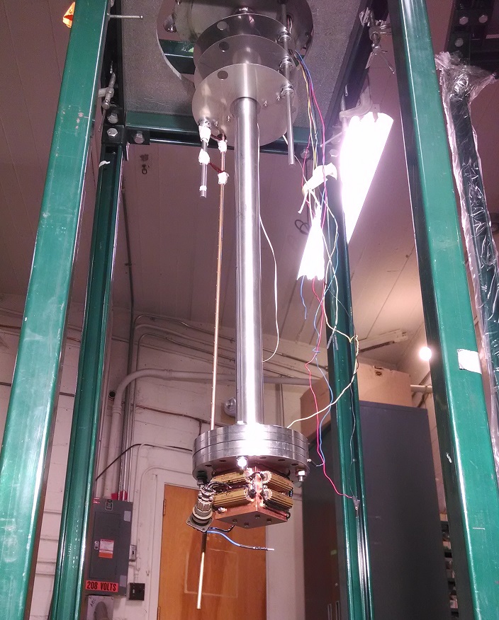
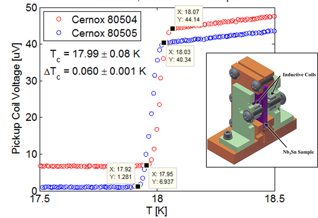
We needed a criterion for evaluating the first samples produced by the Nb3Sn program so that I could optimize the parameters used in the coating process. Critical temperature is a good indicator of coating quality which can be measured much more easily and quickly than RF performance, but there was no Tc measurement apparatus in the lab. Designing and building such an apparatus seemed like an excellent project for summer students, and my advisor was starting a summer program for local community college students. In summer 2011, I was the mentor for Justin Riley, a community college student who designed a Tc measurement apparatus using CAD. The parts for the apparatus were fabricated in the machine shop that year, and then I mentored a second student, Chris Wilson, in summer 2012, who assembled the system and used it to test my first Nb3Sn samples. It worked very well, measuring clear signals with high resolution. It is now also being used by other researchers studying alternative materials, recently proving that nitrogen-doped samples showed the Tc of Nb, not NbN as had been spectulated.
Related publications: Poster and paper at SRF13
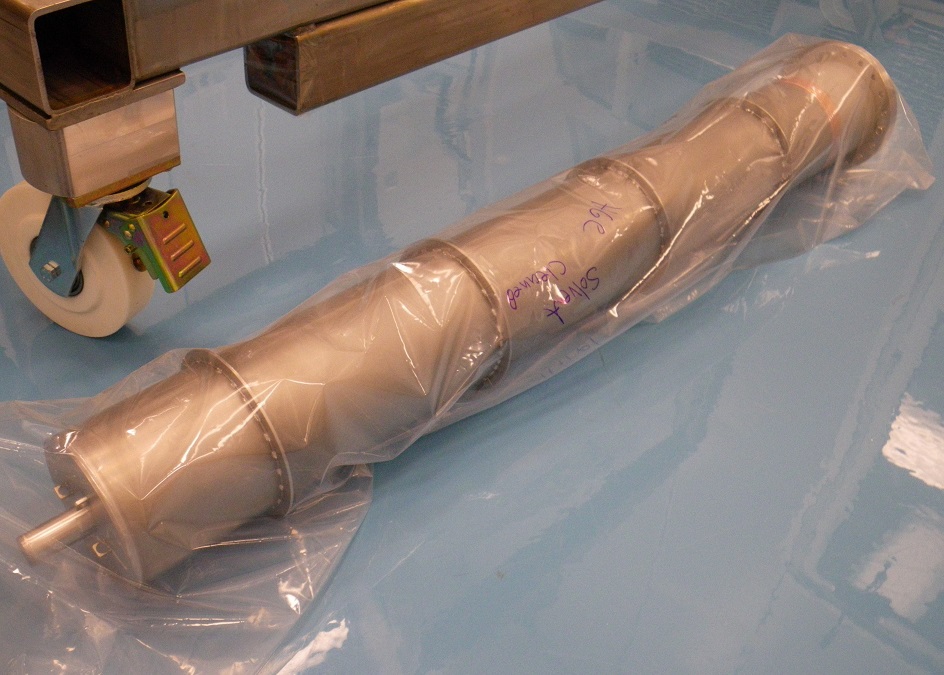
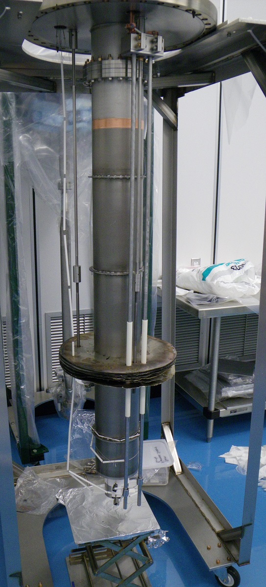
Designing and Building a Nb3Sn Coating System
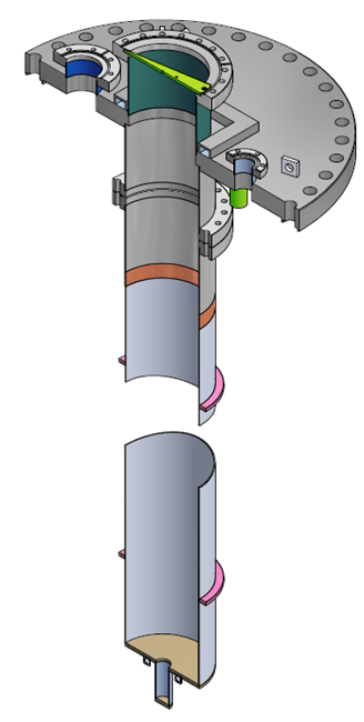
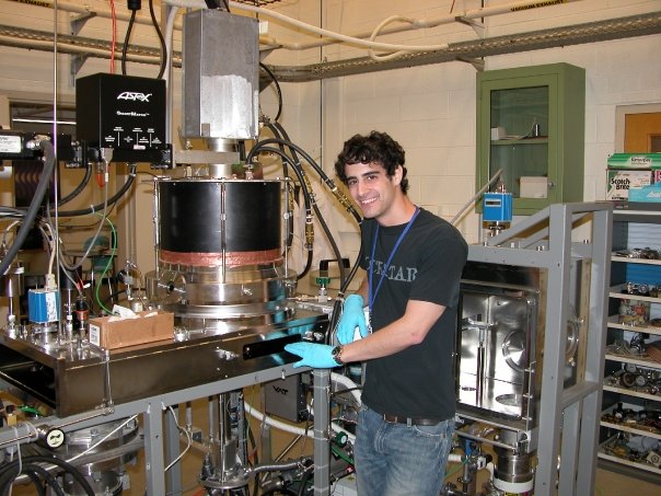
When I arrived at Cornell as a summer intern before starting graduate studies, my advisor already had the idea and the funding to develop Nb3Sn vapor deposition coating at Cornell, but there was no detailed plan. I studied the literature, reading many papers from Wuppertal and Siemens about Nb3Sn-coated cavities. Soon we had an idea of what our coating system should look like, and a way to implement in Cornell's UHV furnace with high likelihood of success. Once the design was finalized, I managed the assembly with the help of a community college student that I was mentoring. I selected and ordered products from vendors, oversaw production of parts in the machine shop, and cleaned and assembled the insert.
Related publications: Talk at SRF Thin Films 2010
Commissioning Nb3Sn Coating System
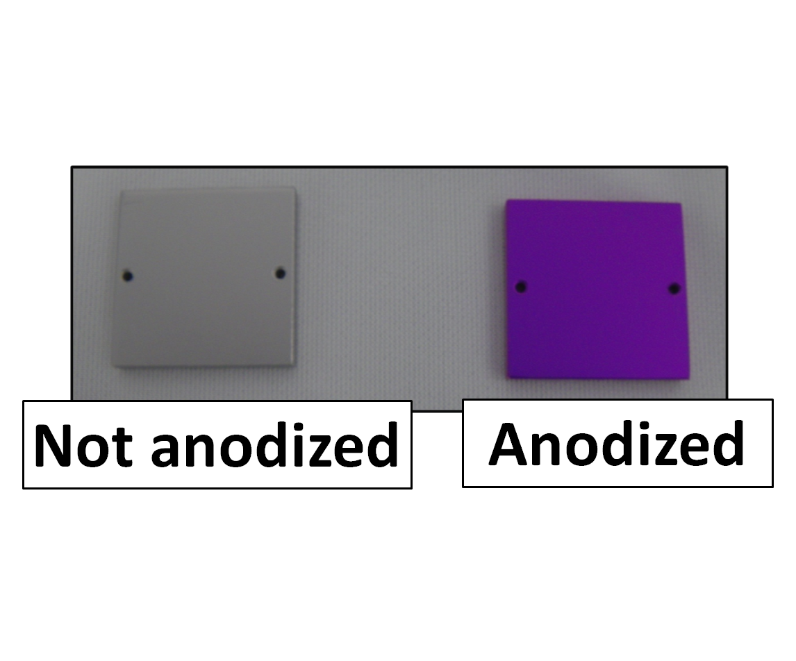
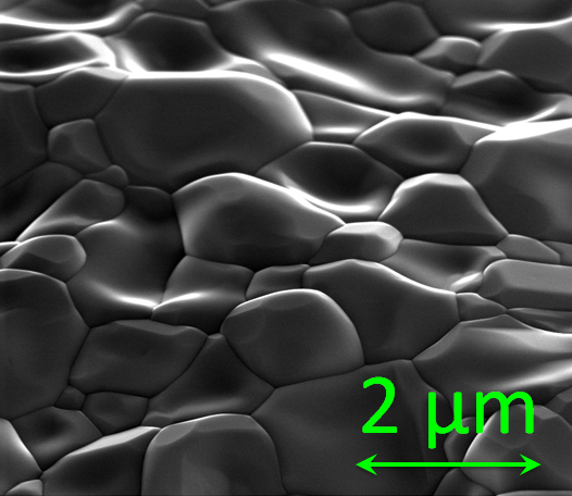
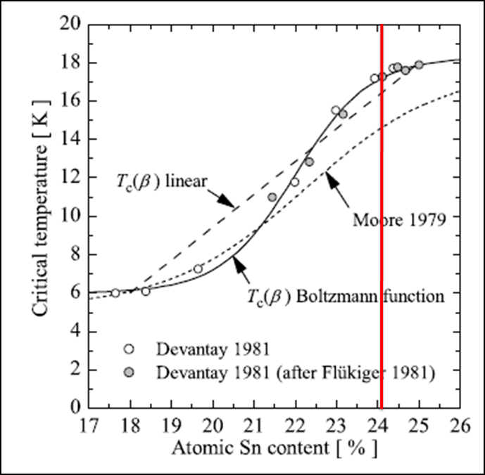
The first samples I coated had excellent properties. Using the Tc system (described above), I measured Tc = 18.1 K, very close to the maximum literature value. Anodization of the samples showed a nice purple color, as expected for uniform coverage, even sides facing away from the tin source. SEM showed good grain structure similar to previous experimenters, and simultaneous EDX showed that over the area of the sample, there was a uniform Sn/Nb ratio close to the optimum part of the composition range. XPS showed a uniform composition down to 1-2 micrometers, which is very large compared to the penetration depth.
Related publications: Talks at TTC 2011 (remote) and SRF11 (award talk), and other conference proceedings at SRF13, IPAC12, IPAC11, SRF11
Nb3Sn Cavity Results
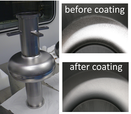
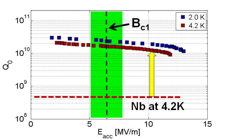
By the time we had established that we could manufacture high quality coatings in a repeatable manner, I had begun the design and fabrication of a new apparatus that could coat full single cell 1.3 GHz cavities. The commissioning was challenging, with our first cavity suffering from what appeared to be problems with the niobium substrate. But my second Nb3Sn coated cavity had extremely encouraging RF performance. I showed that it was possible to produce cavities that did not show strong quality factor degradation with increasing field. That second cavity I produced appears to be the first particle accelerator cavity to strongly outperform niobium at useful temperatures and fields.
Related publications: Invited talks at LINAC14 and NA-PAC13, contributed talks at NA-PAC13, LC2013, and TTC12, and other conference proceedings at SRF13 (1) (2).
HOM Measurements and Cryomodule Assembly
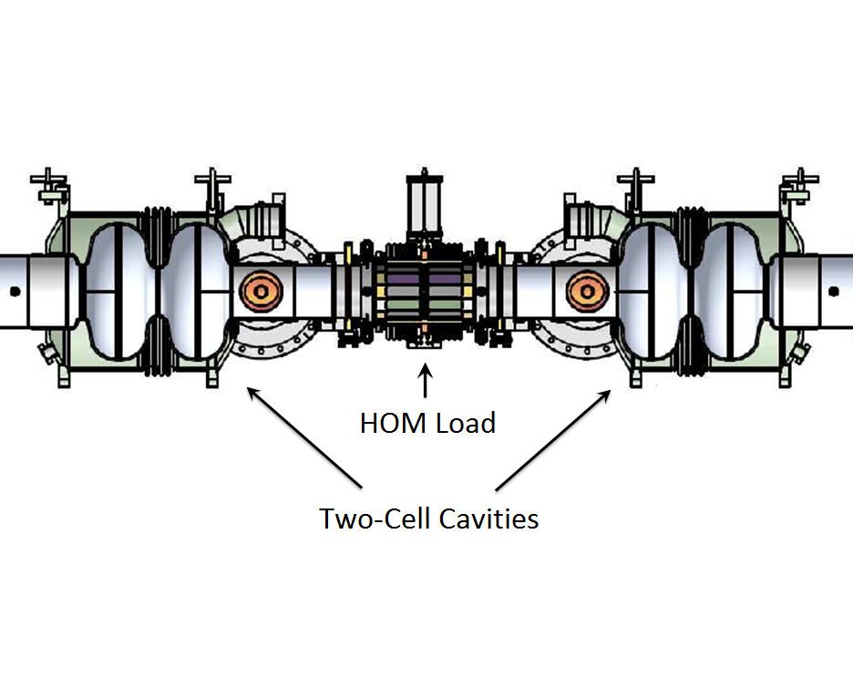
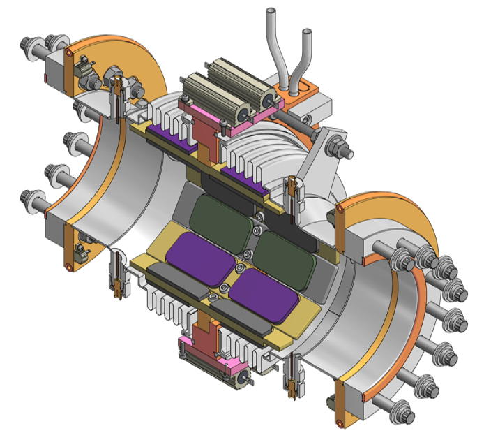
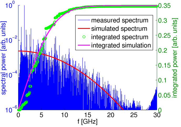
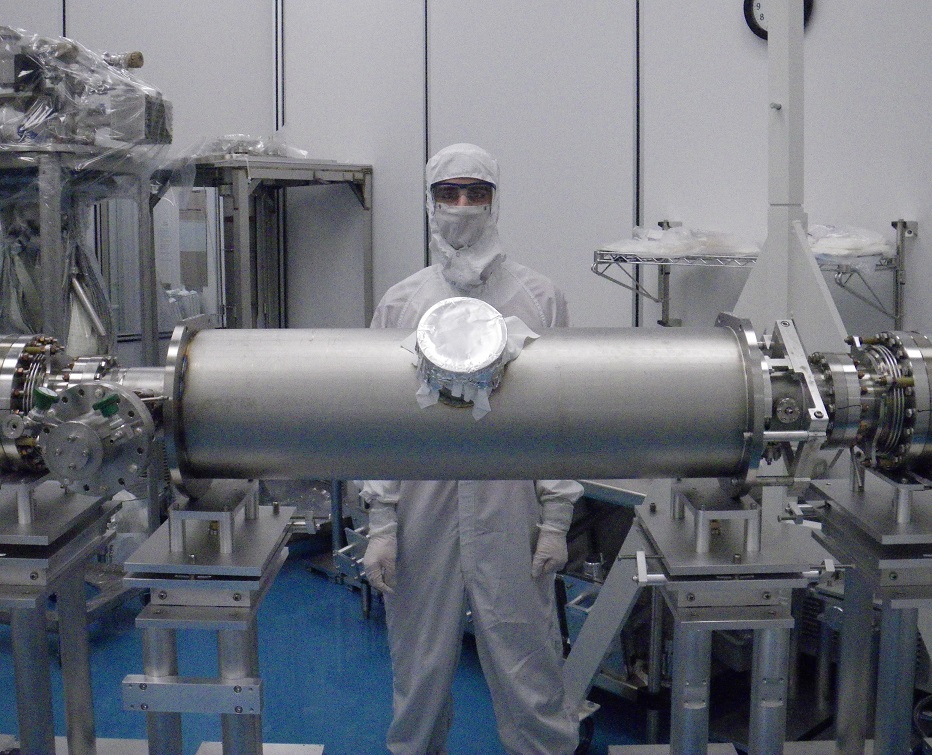
Higher order modes (HOMs) are undesirable high frequency cavity RF resonances that can interact with the beam in harmful ways. They are especially strongly excited when the bunch length is short and the current is high, as they are in the Cornell ERL, which as a result requires extensive use of absorbing HOM loads. I performed measurements of HOMs in the prototype ERL injector cryomodule (ICM), to confirm that the HOM loads provided sufficient suppression over the wide spectrum of frequencies excited by the <1 mm bunches. I used a spectrum analyzer in the secure radiation area to record HOM power as a function of frequency while running as high current as possible through the ICM. No strong lines were observed up to 30 GHz, indicating excellent suppression of all monopole modes. The ICM was fully assembled when I came to Cornell, but I was fortunate to have the opportunity to participate in a cryomodule assembly when the first prototype Cornell ERL main linac 7-cell cavity was tested in the Horizontal Test Cryomodule (HTC). I helped make the key connections of the cavity to the string after high pressure rinsing, learning from the experienced researchers who were leading the assembly the extra precautions and procedures that are necessary for this kind of operation.
Related publications: IPAC12 IPAC11, SRF11, PAC11 (1) (2), IPAC10 (1) (2)
Cryomodule Testing and LLRF
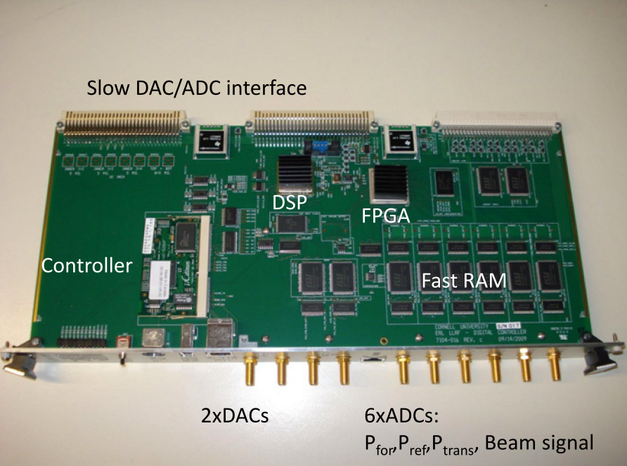
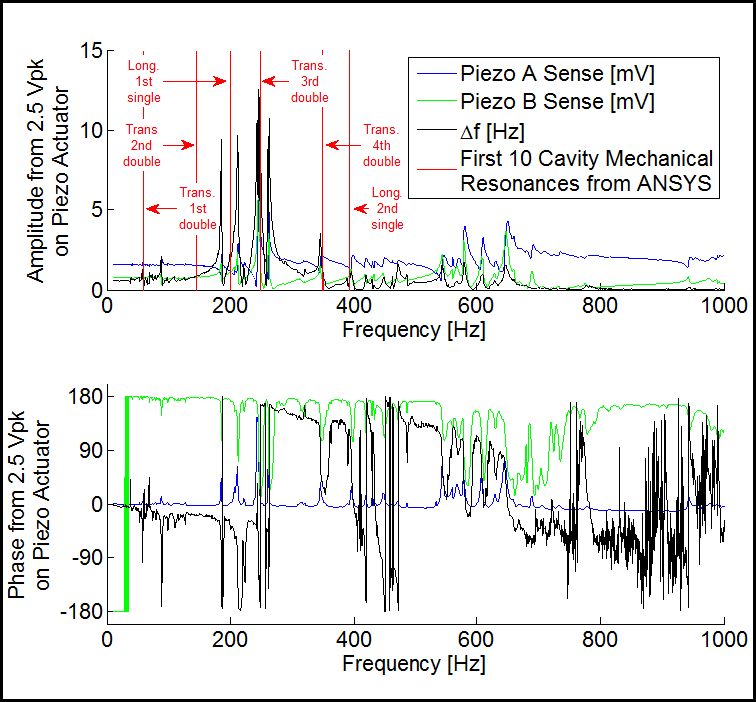
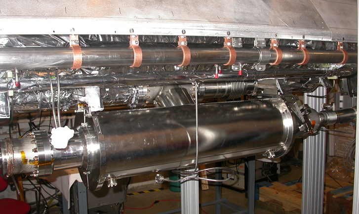
I have been deeply involved in testing of Cornell's Horizontal Test Cryomodule (HTC). When the cavity is interacting with a beam, it is driven at a frequency dependent on the bunch repetition rate. Rather than match the frequency of the drive power to the cavity resonance, we adjust the cavity frequency with a mechanical tuner to match the master oscillator. We use a control loop that varies the drive power to compensate for changes in the cavity frequency and in the beam current. Working with the digital low level RF (LLRF) system of the HTC, I performed detailed studies of amplifier gain control, as well as feedback and feedforward control of the piezos, small devices that quickly change the resonant frequency of the cavity by deforming it. I am fortunate to have had the opportunity to work on the LLRF system with my advisor, who is one of the top experts in the field. I also learned a lot about how to control and evaluate the performance of cavities in this arrangement, and what kinds of problems one can encounter.
Related publications: Nuc. Instr. Meth. in Phys. A, SRF13 (1) (2), NA-PAC13, IPAC12 (1) (2) (3)
Superconductivity Theory
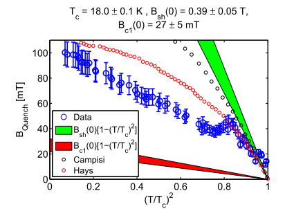
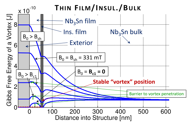
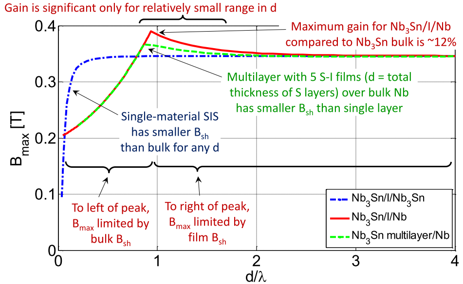
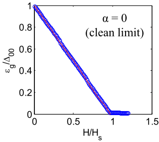
I have been collaborating with Cornell theorists to develop the current understanding of SIS multilayer films. It has been proposed that these sandwiches of thin film superconductors and insulators may allow alternative superconductors to operate at higher RF magnetic fields than they would be able to as an isolated bulk. We have shown that in fact for these structures the lower critical field Hc1 is 0, proving that just like bulk superconductors, they must rely on metastability to avoid flux penetration. We have also shown that for ideal superconductors, the maximum field that can be shielded by an SIS structure is similar to the maximum field that can be shielded by a bulk superconductor. Continuing our study, we hope to determine realistic performance expectations for these structures. In addition, I have applied the theoertical framework of the closing of the superconducting gap developed by Lin and Gurevich to calculate what kind of performance to expect if it were playing a strong role in SRF cavities.
Related publications: Invited talk at SRF13, Contributed talk at SRF Materials Workshop 2012, and other conference proceedings at NA-PAC13
Microwave Equipment
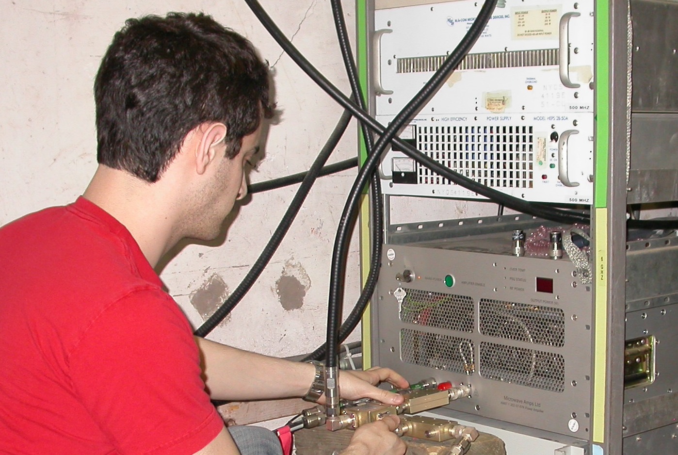
In the course of my graduate research, to operate our cavities at frequencies in the 0.5 - 6 GHz range, I've had to become very familiar with advanced microwave measurement equipment, such as:
- Powerful amplifiers: from 5 kW CW solid state to 1 MW pulsed klystron
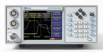
- Boonton 4542 power meters
- Agilent E5071C network analyzer
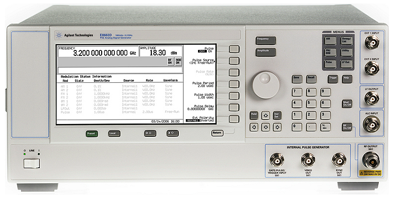
- Agilent E8663D signal generator
- Mixers, phase detectors, directional couplers, circulators, etc.
- SMA, N-type, 7-16 DIN, waveguide connectors
- Fabricating RF cable connector assemblies, including with Andrew Heliax
I've learned to use these instruments in both normal and quite unconventional situations.
Instrument Communication and Process Automation
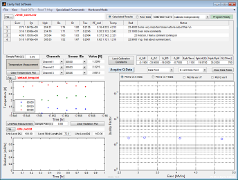
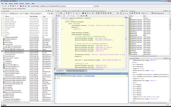
Early in my time at Cornell, I discovered that I could save a lot of time doing complicated but repetitive measurements by writing a MATLAB (or Labivew, C, etc.) script to communicate with a device that will take the measurement for me. For example, during a cavity test, I'll get the PLL to the peak of the cavity's resonance curve, but then the program will take a reading from the power meters, turn them to pulse mode, turn off the signal generator power, wait for the triggered power meter to record a trace, retrieve that trace, turn them back to modulated mode, record incident power, and do the calculation to convert these measurements to Q and E, and then plot the data in a convenient GUI. When myself and another graduate student wrote this program several years ago, we were able to take data much faster and easier, giving us time to do higher quality tests. I use similar programs to measure T-maps, do DC superheating field measurements, run Nb3Sn coatings, and more.
Undergraduate Projects
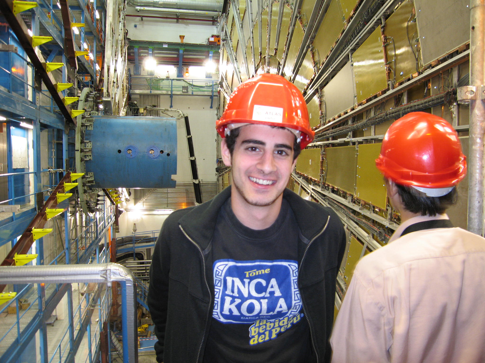
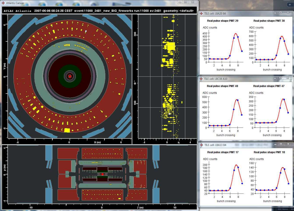
I was fortunate to have participated in some exciting projects in my time as an undergraduate, experiences that have certainly been useful to my graduate work. One of the most influential projects that I worked on was calibration of the ATLAS detector in summer 2007. Analyzing cosmic ray events made me realize that I very much enjoyed working on particle accelerators, but that I wanted to be involved in more hands-on areas. In summer 2008, after developing an interest in alternative energy sources, I worked at the Princeton Plasma Physics Lab on a sputter source, a small experiment that gave me the chance to play a significant role in research. Queen's University's excellent engineering physics program also offered me the chance during the school year to work on many projects that I found fantastically exciting, such as using an actual research fMRI to study fluid flows, calculating the stresses on a Boing 747 airplane wing, and designing a neutral beam injector for a tokamak. Notably, in our senior year, a few of my classmates and I spent a year building a small proof-of-concept cycltron.
Related publications: Talk at CAP 2009 and a LHC ATLAS note.
