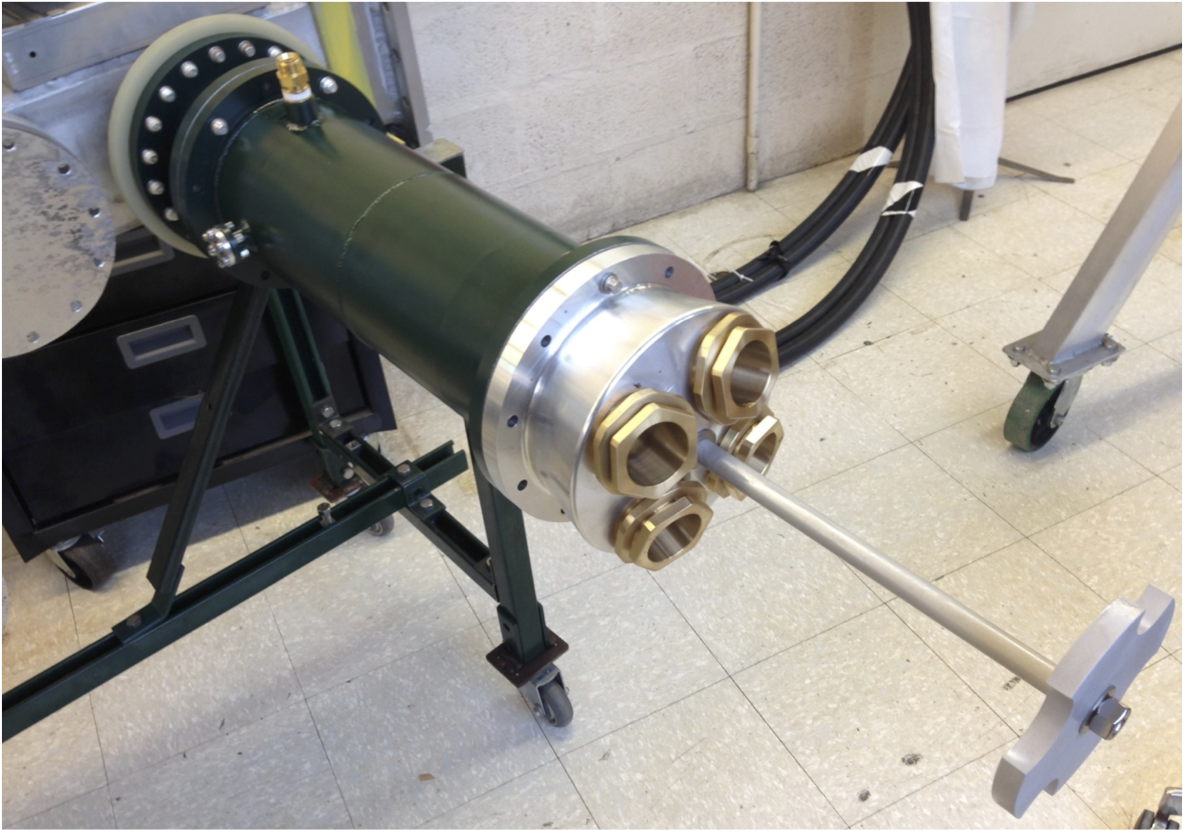
Fig. 1.
The 'bazooka' canister is attached to the vacuum chamber. It accepts four parallel 50 Ohm coaxial cables that extend from the end of the
Blumleins.
The load resistors inside the canister are cooled by fluorinert. The high voltage ceramic feedthrough (not visible in this picture) couples the load resistors to the kicker plates.
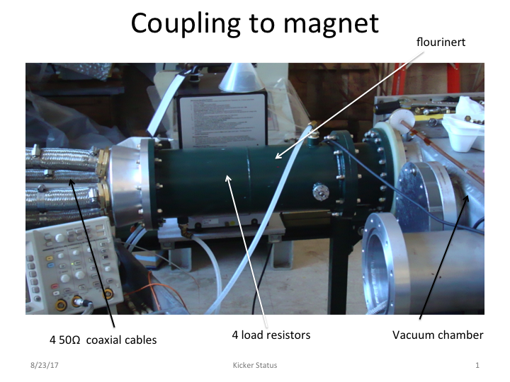
Fig. 2. Cables are connected.
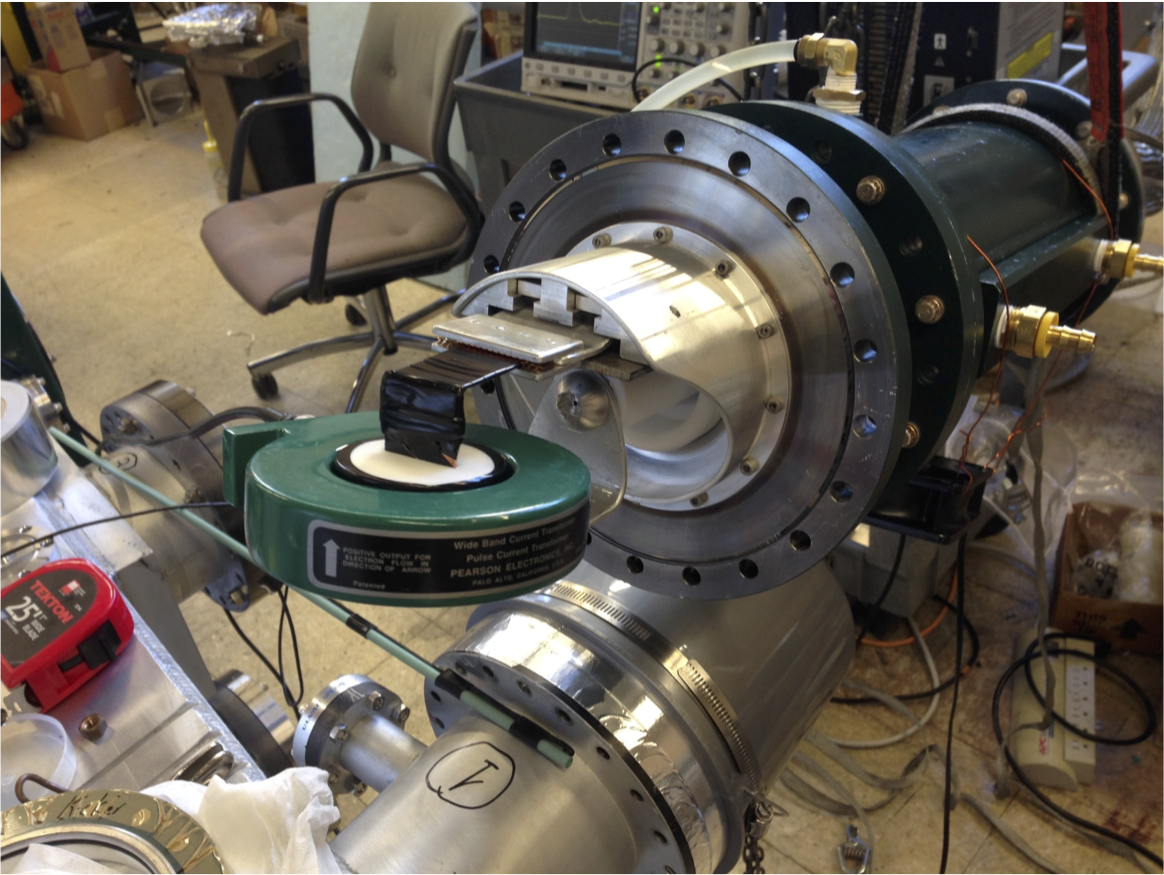
Fig 3. Electrodes are supported inside vacuum chamber by ceramic standoffs. The cross section of the trolley (pink circle) is shown between the plates.
Fig. 4.
View of the end of the HV feedthrough that connects to the vacuum chamber. The electrodes connect to the inner and outer plates of the kicker magnet.
Fig. 5.
View of the vacuum end of the HV feedthrough.
Upper and lower electrodes, in vacuum, couple to inner and outer kicker plates respectively.
Upgrade of HV feedthrough - August 22, 2017 (Hogan) pptx and
pdf
Fig. 6
The dummy load is simply a short circuit between the electrodes that runs through a current monitor.
Fig. 7
Pickup loop. Voltage on the in vacuum loop is induced by changing current in electrode.
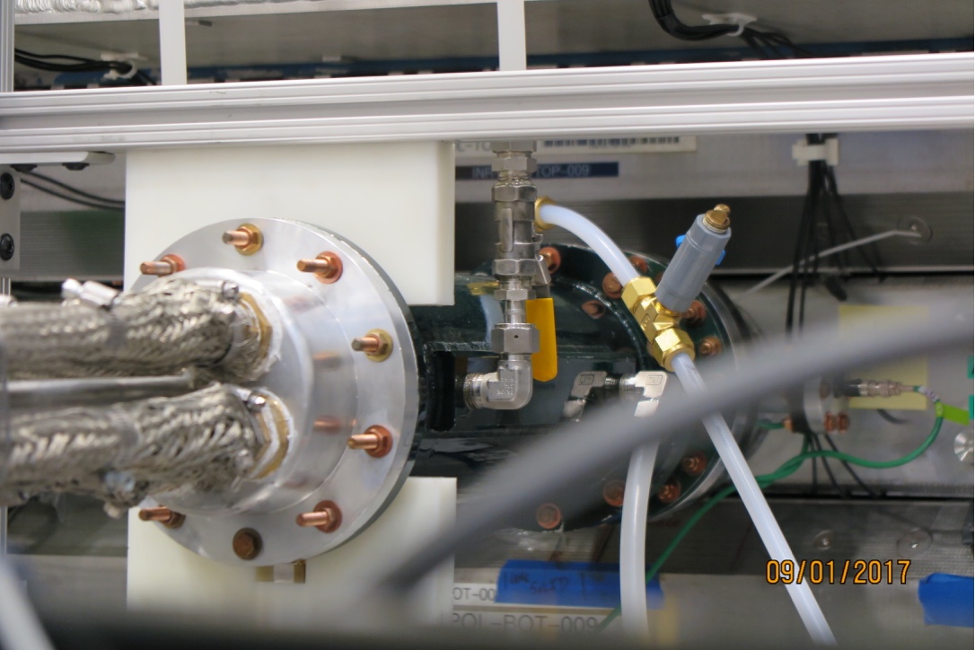
Details at bazooka
Fig. 7. Input to the bazooka showing 4 parallel coax cables. The plastic tubing is for fluorinert. The fluorinert
is cooled by water circulating through the bars welded to
the sides of the bazooka.
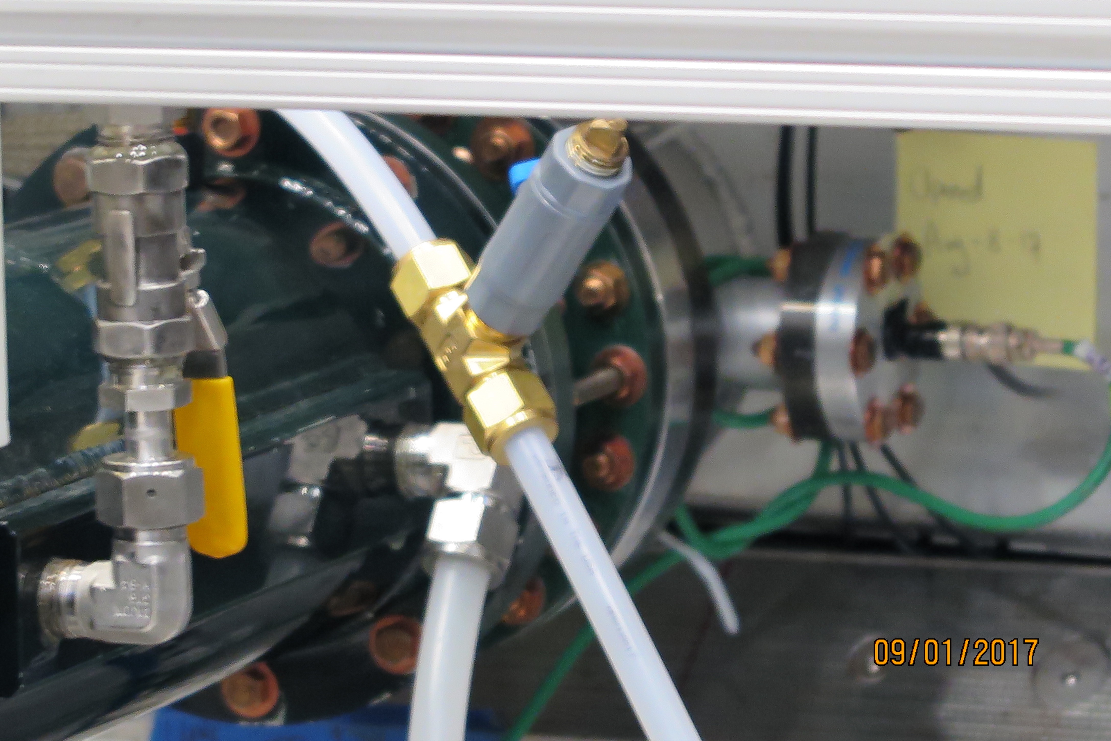
Fig. 8 View of bazooka at vacuum chamber end showing loop current monitor input. This is the signal that
is monitored for sparking. If a spark is detected by the FPGA, trigger to thyratron is inhibited.
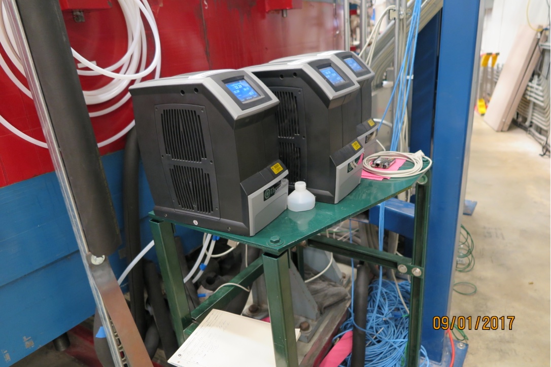
Fig. 9 Fluorinert pumps, one for each of 3 bazookas outside the ring. Note that if the pumps are too close to the magnet the temperature and flow monitoring will fault. If the level of fluorinert in the bazookas drops below the resistors there will be internal sparking that can damage resistors.
Direction of flow is into the bottom of the bazooka and out the top, to prevent formation of air pockets.


