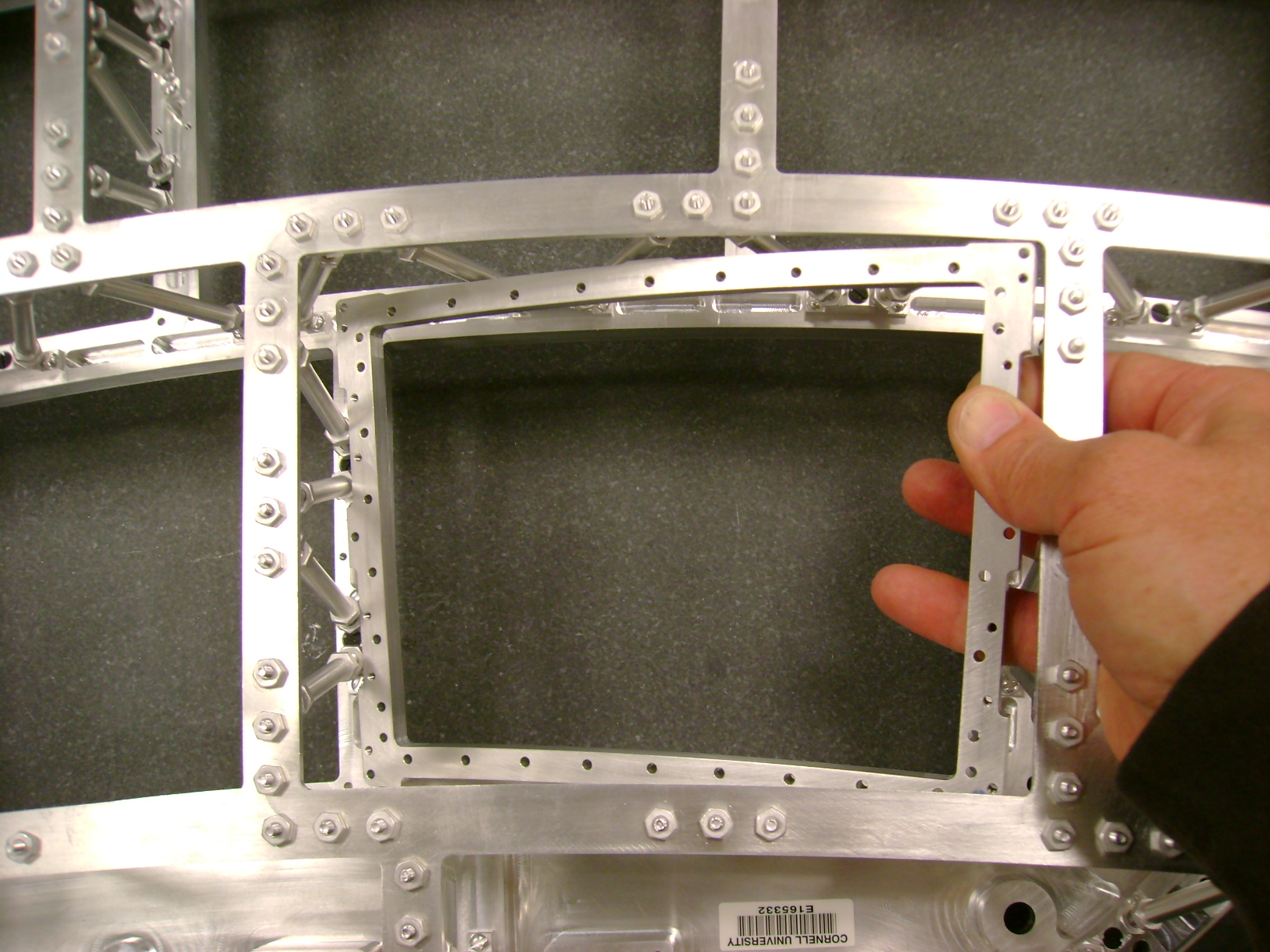
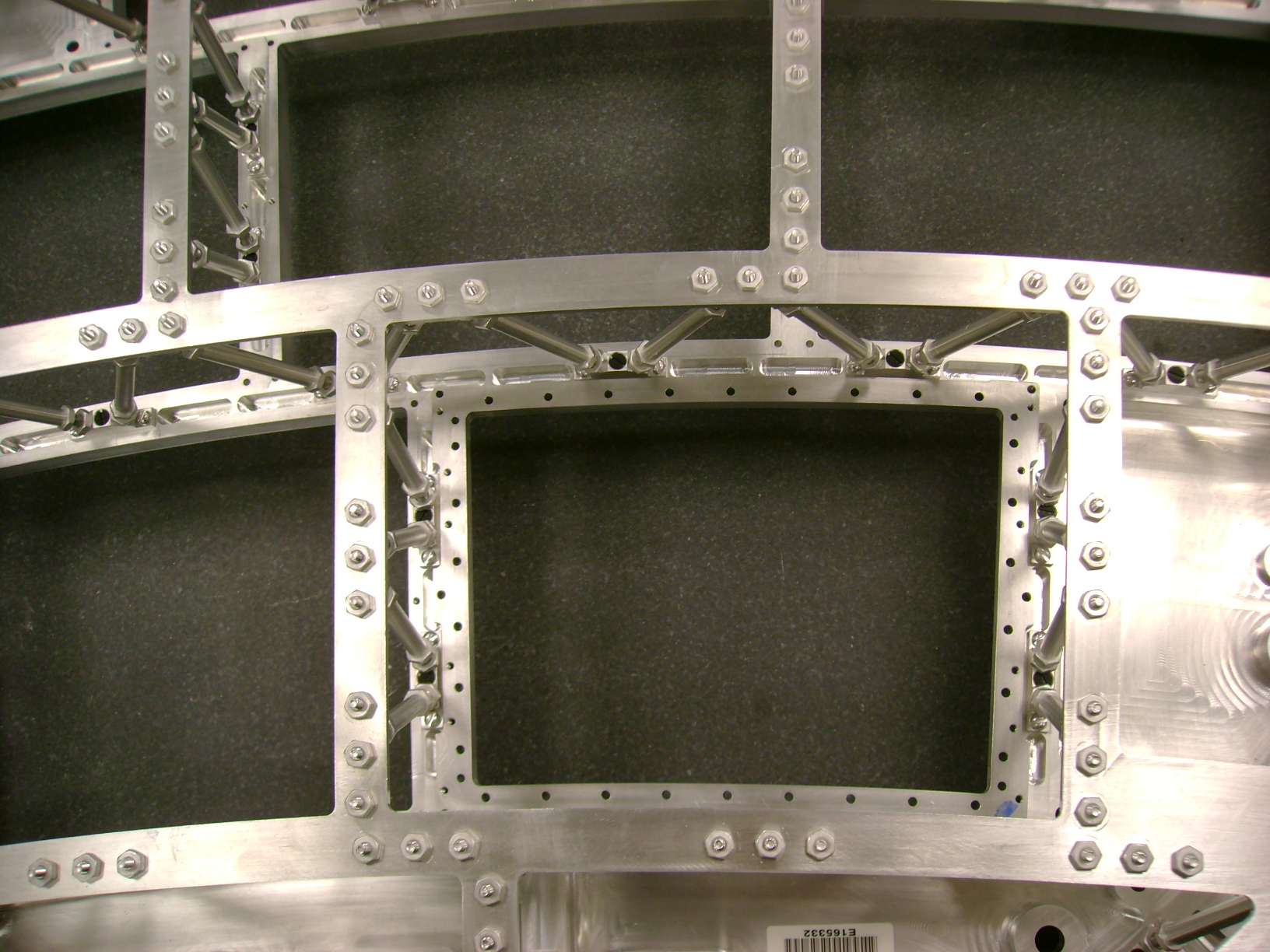
20120308: Horizontal clearance at the location indicated is 198.23mm.
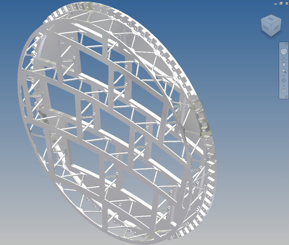
2010-10-29 ILD endplate study
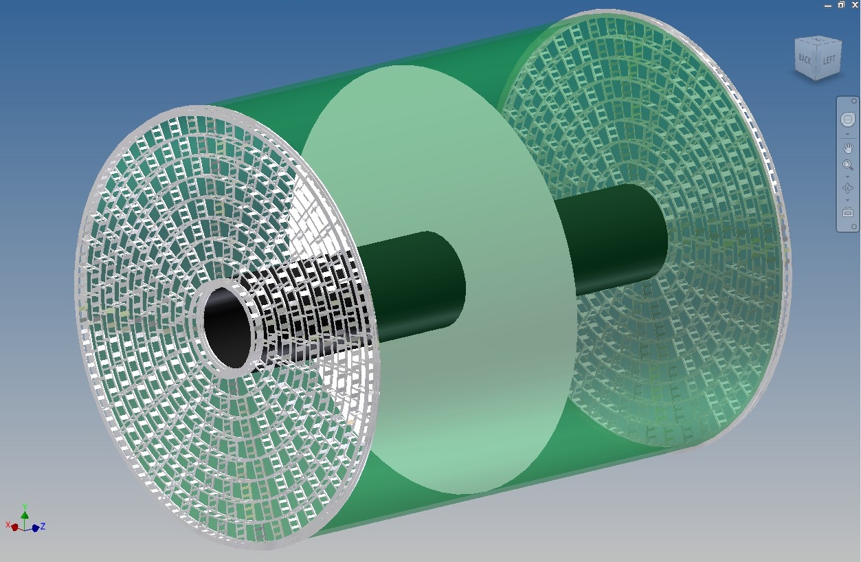
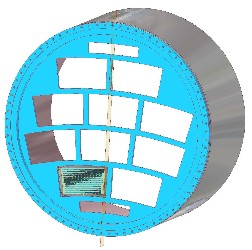
After all the problems with the ILD endplate model have been resolved, this is the ILD assembly figure.

2010-09-23 ILD endplate study
This is the STEP file from 2010-07-01; it is 16MB.
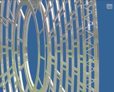
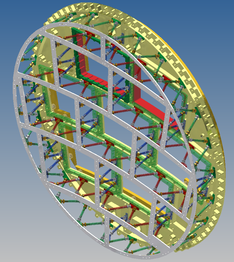
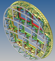
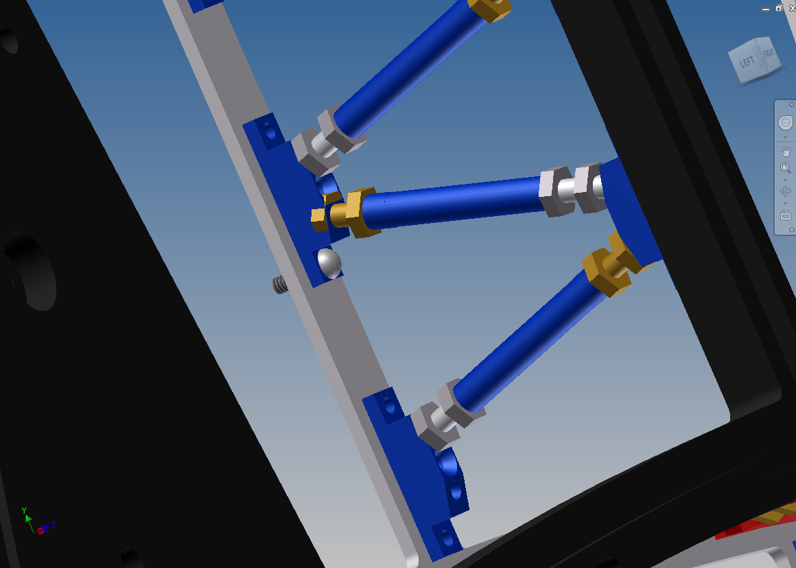
This is the attempt to build the ILD model with "realistic" struts. The model has struts only in the outer ring. With any more struts than this, the FEA is unstable.

2010-05-26 ILD endplate study
Added Back-Disk and outer ring of struts.
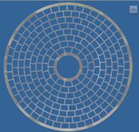
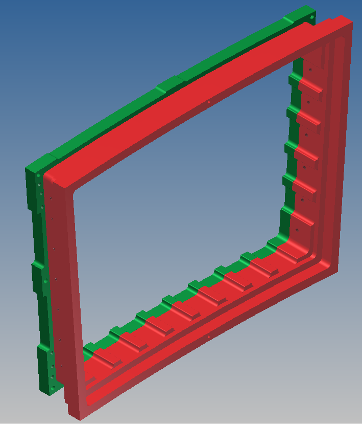
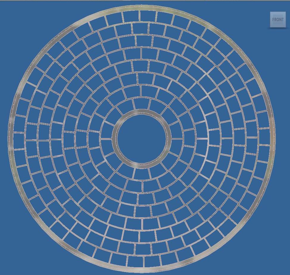
The module widths are slightly changed in each row; areas are now betwen 96% and 101% of the LP1 module area. Starting angles be adjusted to minimize the lining-up of boundaries in adjacent layers.
Total thickness is 100mm. The finite element analysis crashes; I will have to simplify the model for the FEA.
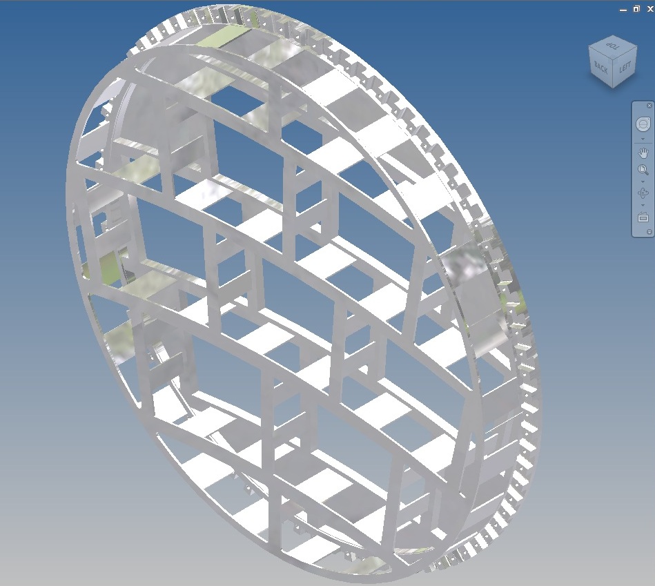
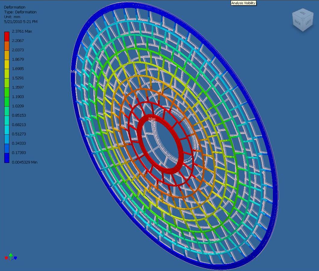
2010-05-21 ILD endplate study
A model has been started with LP1-size modules. So-far, it is without the space-frame support.
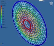
The result of Finite Element Analysis is shown in the figure. The total load in the analysis is 100N. This is the same total force value I was using for the LP1 tests. It should be scaled up by a factor of 22 (the ratio of the area of ILD to LP1) for 2mbar pressure. The deflection is (2.3mm x 22)= 50mm.
(purdue)
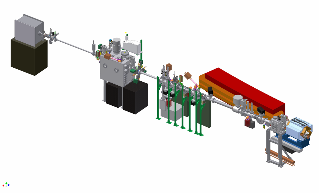
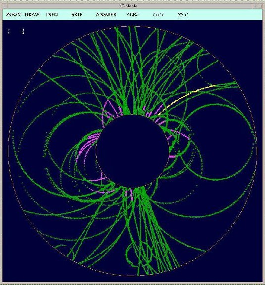
xBSM

(DESY-FLC-TPC)
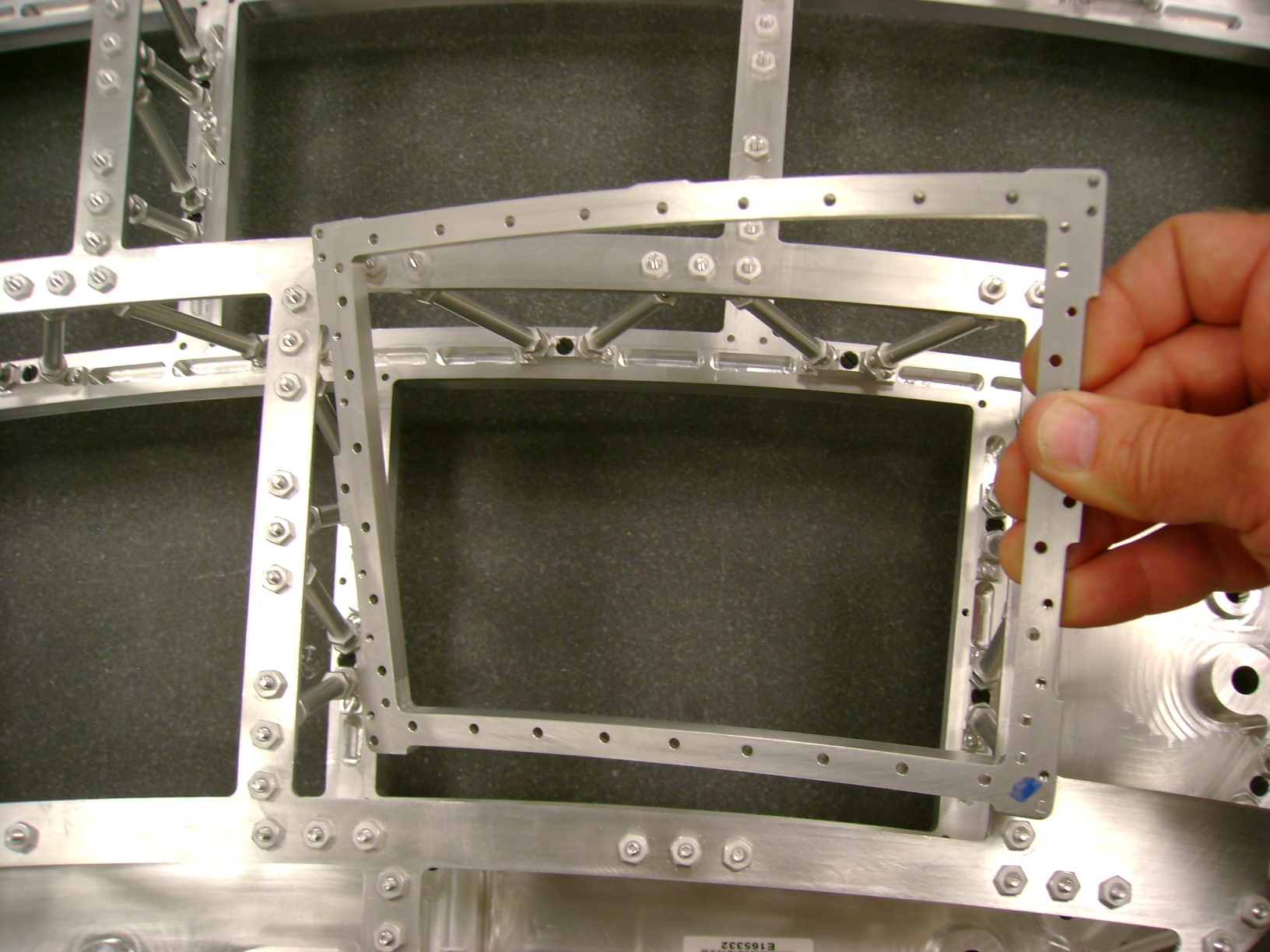 step 1
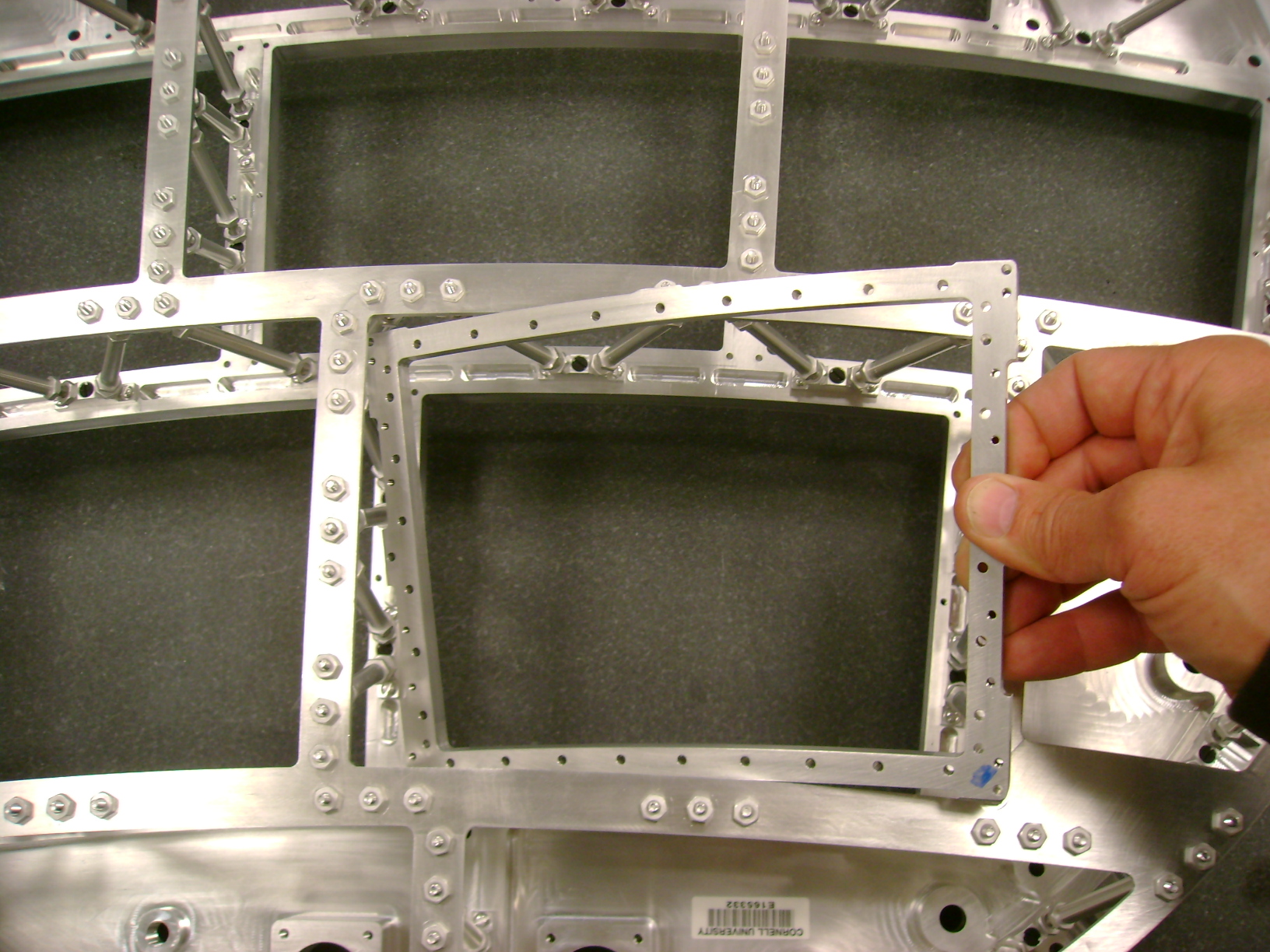 step 2
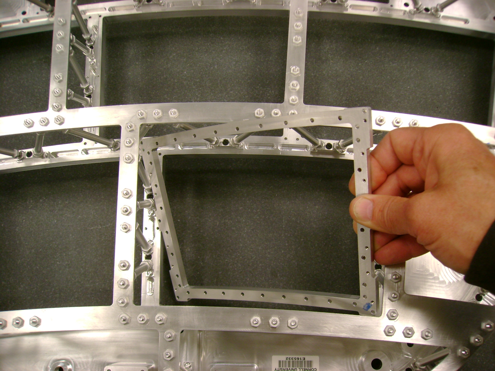 step 3
 step 4
 step 5
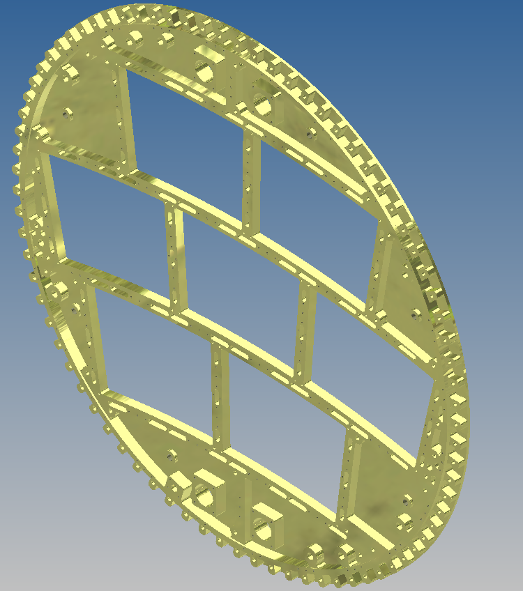
 LP2 solid model
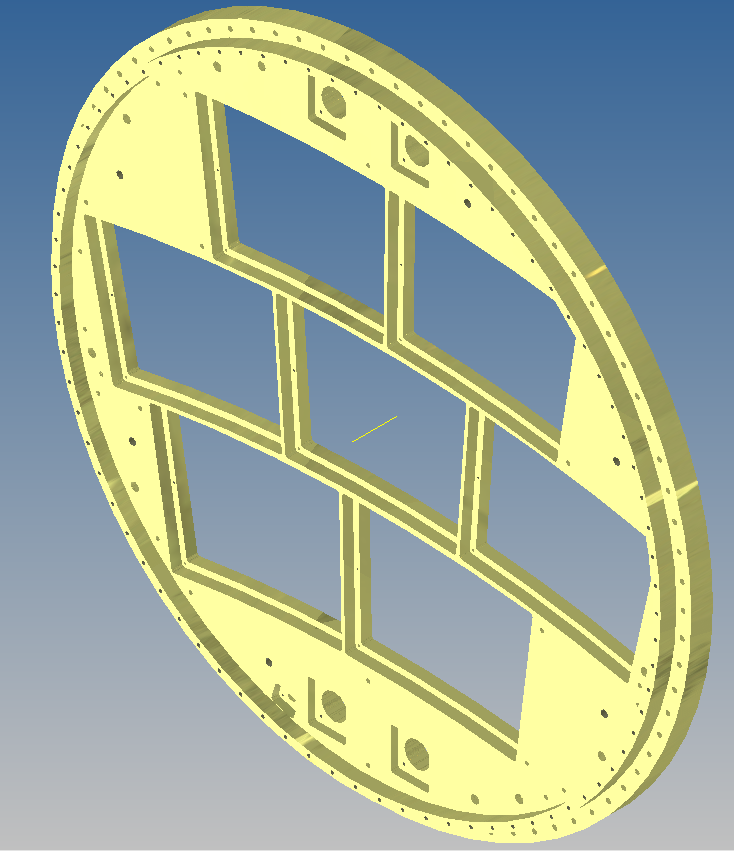
 LP2 equivalent plates model


