Lab Window
 ISSUE 2 - OCT 1997
 - Produced By Ruth Sproul
On the eve of our tuneup with CESR's first Superconducting RF cavity, this seems a good time to take a quick look at some lab history.
(Click for movie)
Superconducting RF work at the lab was started as a research project by Maury Tigner around 1969. For the first major project, around 1975 we built and installed a superconducting RF cavity in the synchrotron (CESR was not yet built). This was the first SRF cavity ever operated in an HEP machine. There was a lot of doubt as to whether a superconducting cavity would hold up in the environment - or whether it would ruin itself with accumulated vacuum crud from the rest of the machine. The experiment was a big success - the cavity was run continuously for several weeks, and left in the machine for several months and then retested and it held up ok. Half of this cavity (an 11 cell muffin tin structure) now sits in the showcase on the third floor of Wilson lab. This cavity was machined out of solid niobium, which was time consuming and expensive, so our RF group developed methods for making cavities out of sheet metal. It was clear after the experience with the synch cavity that a good deal of fundamental research on the properties of niobium surfaces was needed to reach the necessary acceleration fields. At that time, Maury Tigner formed an SRF group to specialize in this area.
But the effort to build CESR consumed most of the SRF group. Ron Sundelin, Joe Kirchgessner, Larry Phillips and Maury Tigner all went to work on CESR, and Hasan Padamsee was the sole person left to maintain forward momentum on the Superconducting RF project along with some visiting scientists. Hasan kept the effort going, so that when CESR was done and manpower was available again around 1980, we didn't have to start over from scratch.
When CESR was completed, the SRF group regrouped and Joe Amato, Peter Kneisel and Charlie Reese joined the group. They built a cryostat for two 5-cell 1.5 Ghz muffin tin cavities, and did a beam test in CESR. This was the first Superconducting RF cavity ever tested in a Storage Ring. A lot of stability questions were answered, but the muffin tin shape had multipacting problems, so they switched over to an eliptical circular design for cavities, built some 5-cell cavities and did another beam test in CESR. This design allowed us to go to twice the voltage and behaved quite well - it was designed for a hypothetical 50 Gev e-e+ storage ring. That cavity was adopted by
CEBAF in VA and now they have 350 of them running in their machine. Many people from the SRF group left to work on the CEBAF project - Hasan and Joe K. chose to stay with us, and again expanded the group with additional staff and several scientific visitors.
(Click for movie)
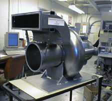
The SRF group continued to do a lot of fundamental studies - trying to understand field emission and thermal breakdown. The SRF cavities for CESR (the first is now installed) are single cell cavities that were originally designed for our proposed B-factory. The SRF group took that basic cavity design and worked out the cryostat design, and in 1994 did a beam test in LO that was a success.
The main reason for going to SRF cavities is to raise the total current we can put into CESR, by reducing the total impedance of the cavities (by reducing the total # of cells in the machine and by reducing the parasitic interaction with the beam). The current in CESR is limited by instabilities, and the instabilities are dependent on the impedance of the ring. The biggest culprits for perturbing the beam now are the RF cavities. Going from 4 x 5-cell RF cavities to 4 x 1-cell SRF cavities will lower the impedance to the beam by a factor of 4, and the shape of the new cavities will lower the impedance by another factor of 2 or 3. We hope to reach 1 ampere total current in CESR with 4 SRF cavities in the machine.
Superconducting RF cavities are not perfectly efficient (as superconducting DC magnets are), but the loss is small - the dissipation in each of our SRF cavities will be about 100 watts compared to about 70,000 watts for an equivalent (5-cell) copper cavity. The cryo heat leak loss will be another 30-50 watts, so helium cooling will need to provide about 150 watts of cooling.
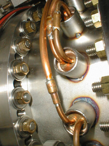
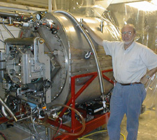
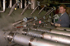
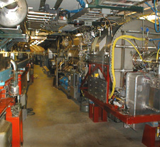
During the processing of our first SRF cavity, just prior to installing it in CESR, both the cryogenic (cooling) system for the cavity and the cavity itself were checked. For the cryogenic system we learned: how to operate the helium refrigeration and distribution system, how to cool down the cavity, how to keep the helium level inside the cryostat constant, and how to keep pressure inside the cryostat constant. The cryo system is designed such that the cold helium is sent to the cavity in liquid form, cools the cavity and in so doing turns to gas form. We send the gas back to the refrigerator to be cooled back down to liquid, then send the liquid helium back to the cavity, etc. When we look at the SRF cavity, what we're really seeing is the shape of the cryo jacket that envelopes the cavity, and which is itself insulated from the surrounding air temp by 60 layers of insulating mylar and a layer of insulating vacuum. The cooling for the cavity is a closed system, where the helium experiences a very small temperature change, going just back and forth between liquid and gas states, with virtually no loss of helium.
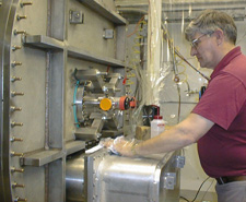
For the cavity itself, we learned how high an electric field we can put into the cavity, and looked at what will be the Q factor (quality factor). The cavity was processed both in continuous power mode and in pulse mode, and both results were very positive since they were beyond design specifications. Continuous power processing reached 8 megavolts per meter (design was 6 megavolts per meter), and in pulse mode we reached 11 megavolts per meter.
(Click for movie)
The Q factor for an RF cavity characterizes the quality of the cavity according to the measured RF losses in the cavity. An SRF cavity should have very low RF losses. The Q factor could be thought of this way: if there were 2 RF cavities that were built with the same shape, but made out of different materials (say, copper and stainless steel) then the field distribution inside the cavities would be the same but the measured RF losses would be very different, because the resistivity of stainless steel is much higher than that of copper. To characterize this type of difference, they came up with this Q factor number. The higher the Q factor number, the better the cavity. Our SRF cavities are made of pure niobium, one of the best metals to achieve high Q in superconducting conditions. Hasan likes to say that if the level of efficiency of our Superconducting RF cavity were translated to a pendulum oscillating at a period of one second, it would take 100 years to ring down (our SRF cavity period is 1 nanosecond, however). Q factors for SRF cavities are notoriously fickle to nail down, since this number is influenced not only by the cavity itself, but by other factors in it's environment.
(Click for movie)
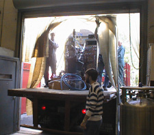
The installation of the first Superconducting RF cavity in CESR is the beginning of another era in the history of CESR, and will allow us to push the beam currents higher and produce more luminosity.
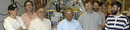
Our SRF group members are recognized worldwide as leaders in Superconducting RF research and application. Their talents have made this advancement possible for us.
So, crank up the current. As the operators say, let's find the next thing to break.
-Ruth Sproul
Superconducting RF info was supplied to me primarily by talks with Joe Kirchgessner and Sergey Belomestnykh.