3: Present Limitation: Field Emission
With the problems described in the last section overcome, the primary limitation of the last five to ten years has been field emission (FE) of electrons out of the niobium surface in the presence of high surface electric fields. FE loading is detrimental for several reasons. Emitted electrons impact elsewhere on the cavity surface, heating the surface, and therefore increasing the surface resistance. This increases power dissipation of the cavity, as well as adding to the load on the refrigerator. In extreme cases, FE heating of the cavity walls can lead to thermal breakdown, as described in the last section. Acceleration of emitted electrons absorbs power out of the electromagnetic fields which would otherwise be available for acceleration of the particle beam. Eventually, as fields are raised, the power dissipation into FE related processes limits the attainable fields in the cavity.
3.1: Fowler-Nordheim Theory
The emission of electrons from a metal-vacuum interface in the presence of an electric field normal to the surface was intially treated as a quantum mechanical tunneling process by Fowler and Nordheim.
[32] Their theory predicted the field emitted current density, in equation 10, and the total current, equation 11.
/www/pub/Home/Research/SRF/SrfCavitiesAPrimerThree/Eq1011.GIF
where
E is the applied electric field, phi is the work function of the metal,
C and
B are constants,
A is the emitter area,
/www/pub/Home/Research/SRF/SrfCavitiesAPrimerThree/Eq10a.GIF, and
v(y) and
t(y) are functions which arise due the inclusion of image charge effects.
v(y) and
t(y) are near unity for typical conditions, and therefore standard practice is to omit them. We follow that convention here.
According to these expressions, however, field emission should only reach hundreds of microamps, which is necessary for significant loading of an RF cavity, for fields higher than 10,000 MV/m (assuming an emitter area of 10E-10 sq cm). Experiments showed that in real systems this level of emission occurs at fields as low as a few MV/m.
In order to explain emission at low fields within the Fowler-Nordheim model, an "enhanced" version of the theory was proposed.
[33] In the enhanced Fowler-Nordheim picture, the mechanism is the same (quantum mechanical tunneling), but a local field enhancement factor beta is introduced. The emission current density is then given by equation 12, and total current is given by equation 11.
/www/pub/Home/Research/SRF/SrfCavitiesAPrimerThree/Eq12.GIF
Initially beta was postulated to arise due to geometrical effects at the surface. The enhancement due to geometrical irregularities on the surface (e.g. hemispheres, cylindrical projections, etc.) can be computed
[34]-[36]. Comparison of measured values of beta from the field emission current (which were often several hundred to a thousand), with geometric asperities at the surface failed to produce any features which could result in enhancements of this magnitude.
Local field enhancement has also been predicted due to contaminants and defects on the surface of the metal. Models
[37] have been proposed which introduce field enhancement due to semiconducting or insulating materials on the metal surface. In addition, surface contaminants are capable of altering the work function of the surface, thus producing similar effects to a field enhancement.
The present best model of the enhancement allows for both geometrical and material mechanisms of field enhancement. Furthermore, while no definite physical significance can be attributed to beta or
A, they are still useful quantities for characterizing the nature of emitters, as has been done extensively in previous studies.
3.2: DC Field Emission Studies
A great deal of study has been performed in the area of field emission out of metal surfaces under DC conditions. The investigations generally fall into one of two categories: studies of field emission and studies of vacuum breakdown or explosive emission. These two categories are related in that explosive emission is best explained as field emission extended to conditions such that the emission becomes explosive in nature.
Studies of niobium electrodes under high field DC conditions were performed by Ph. Niedermann.
[38],[39] The apparatus was constructed such that it could be examined via field emission measurements, scanning electron microscope, and scanning tunneling microscope without vacuum break. This project has shown a clear link between surface contaminants and field emission. In addition, the studies of heat treated niobium electrodes helped lead to the use of high temperature vacuum baking as a successful method of RF cavity preparation. This will be discussed further below.
Further in depth studies of DC emission have been performed by the group of Latham.
[40]-[42] From this work has come several models of non-geometric mechanisms of local field enhancement. In addition, extensive studies of gas conditioning of electrodes were performed.
Vacuum breakdown refers to processes where high DC voltages under vacuum conditions result in an arcing process. We will show later in this dissertation that this phenomenon is analogous to RF processing. Extensive studies have been performed in this area, therefore we will only discuss those phenomena which will prove useful for comparison with the results to be detailed later in this thesis. Comprehensive reviews of this field are available.
[34]-[36],[43],[44]
Examination of cathodes which have been exposed to high electric fields and the associated arcs has revealed extensive cratering.
[34],[35],[45],[46] The craters have characteristic sizes on the order of microns. Often the craters are overlapping, showing multiple events. The explosive nature of emission processes on cathodes is clearly verified by the detection of craters.
The time required to initiate an arc has been measured
[47],[48] to vary from microseconds to less than nanoseconds, with the initiation time decreasing with increasing electric field (or increasing emission current density). Further measurements on niobium surfaces
[47] show that superconductivity of the cathode surface does not effect the initiation time for explosive processes.
Modelling of explosive processes and the ensuing plasma
[35],[43] predict thermionic emission of electrons from the plasma cloud with velocity on the order of 108 cm/s. Nearly all modelling of explosive processes has been of pure metal vacuum interfaces, with field enhancement entirely due to geometric effects. The limitations of modelling only this type of emission have been pointed out,
[36],[46] yet only passing reference is made to other sources of emission, such as surface contaminants.
3.3: Twenty Years of Knowledge in Avoiding Field Emission
Superconducting RF cavities have been in use since the late 1960's. In that time, as other limitations have been overcome, significant progress has also been made in reducing FE loading of cavities.
The most important gains, both in understanding and improved performances, have been in the area of surface cleanliness. The DC studies described in the last section clearly showed the link between contaminants and emission, therefore great effort has been put forward to reduce sources of contamination to the cavities. Cavities are now assembled in clean rooms in order to minimize atmospheric contaminants. Rinsing of cavities is perfomed with high purity liquids (e.g. deionized water or methanol).
High temperature vacuum baking of the cavity is another method of reducing surface contamination. This procedure was drawn from the DC studies of Niedermann as listed above, and in that work it was clearly shown that the effect of high temperature baking was to reduce the number of surface contaminants. Studies of heat treatment preparation of RF cavities to reduce FE at Cornell
[49],[50] and Wuppertal
[29] have shown significant gains in achievable surface electric fields.
Low power RF processing (up to 100 watts CW power) has also been used with some success in SRF cavities. Unfortunately, the exponentially increasing power dissipation due to field emission quickly utilizes all available power. The mechanism of the processing was not well understood until recently.
Helium processing, or RF processing in the presence of a partial pressure of helium (1e-5 torr), has been shown to be successful in increasing attainable electric fields by ten to twenty percent above their original values. This mechanism is not yet clearly understood. It was originally believed that the helium ions sputter the RF surface, removing condensed gases, or other contaminants. More recently, Latham has postulated that helium becomes embedded in the RF surface
[42], creating electron traps, which inhibit emission. The effect of helium processing on individual sites has been shown to be reduction in field enhancement beta.
[50],[51]
Further gains in attainable accelerating gradient have been achieved through alteration of cavity geometry in order to minimize the ratio of peak surface field to accelerating gradient. In this manner, accelerating gradient is maximized with respect to the maximum surface electric field.
3.4: Thermometry as a Tool for SRF Cavity Investigation
As SRF technology has advanced, thermometry has emerged as a valuable tool for investigation of cavity behavior. Many phenomena of interest dissipate sufficient power in the cavity so that a temperature signal may be measured by sensitive thermometers located at the cavity/helium interface. Thermometry studies have been performed at many laboratories,
[52]-[55] both with fixed and movable arrays of thermometers.
Field emission phenomena are observable, because emitted electrons are accelerated by the electromagnetic field and then impact elsewhere on the cavity surface. The power deposition from electron impact can cause measureable temperature rises at the outer surface of the cavity. The thermometry signal can be modelled via solution of the relativistic equations of motion of the emitted electrons in the cavity fields, combined with heat transfer models within the niobium-helium system. Comparison of measured and simulated signals yields further information on the nature of the emission sites.
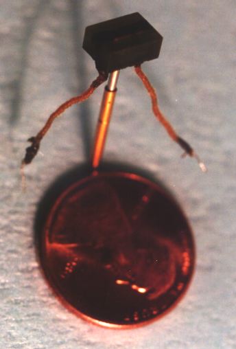
The thermometers used in SRF cavity mapping are constructed of 1/8 watt resistors, encased in epoxy in a G-10 board shell, and then mounted on a
pogo-stick, a spring-loaded rod. The resistive element is exposed thermally, but insulated electrically by a coat of varnish.
The thermomers are then mounted via their pogo-stick into a board which is shaped to put the thermometers into a regular array around the cavity.
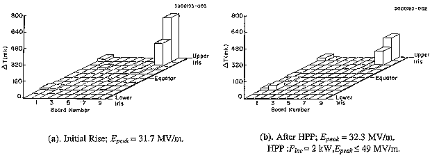
The readout of the thermometers can then be read as a
map of the cavity surface. Examination of change in thermometry signals as a function of field strength inside the cavity provides a good characterization of the cavity behavior. A typical thermometry map (showing the reduction in heating following HPP processing) is shown below.
3.5: High Vacuum Heat Treatment (HT) of SRF Cavities
The connection between contaminants on the RF surface of cavity and field emission from that surface has been well established over the last 10-15 years. Given this connection, much of the basic research on SRF cavities has centered on the question of producing a cleaner RF surface.
Excellent results were obtained through the use of high vacuum
Heat Treatment (HT) of cavities (T in excess of 1400 degrees C), both at Cornell University and at Wuppertal University. Thermometry studies of cavities following HT showed marked reductions in field emission loading. HT cavities have reached surface electric fields of 60 to 75 MV/m with little or no field emission.
In addition, studies of DC field emission at Wuppertal have further shown that heat treated surfaces not only are cleaner, but are less likely to emit from those contaminants which are still there. The mechanism of this field emission suppression is not currently understood.
Heat treatment is normally done with some sort of protection against degradation of the bulk niobium of the cavity. Without this protection, the RRR (and therefore the thermal conductivity) of the cavities would decrease due to absorption of oxygen from the furnace, making the cavity more susceptible to thermal breakdown following heat treatment.
The protection scheme of the cavities during HT is to surround the cavity with a titanium foil, which will create a vapor during the heat treatment. The titanium will coat the surface of the niobium, and since it has a higher affinity for oxygen, it will prevent migration of oxygen into the bulk material. The titanium oxide is generally removed (with an acid etch) following HT.
Heat treatment with titanium only on the outside of the cavity will maintain a constant RRR, while HT with titanium inside
and outside the cavity will actually increase the RRR of the cavity.
3.6: High Pressure Rinsing (HPR) of SRF Cavities
Not Ready Yet!
3.7: High Power RF Processing (HPP) of SRF Cavities
High Power RF Processing (
HPP ) of
S uperconducting
R adio-
F requency (
SRF ) niobium accelerator cavities was studied by
Joel Graber as his Ph.D. dissertation research.
The problem under study was the following:
SRF accelerator cavities present
several advantages to their normal conducting counterparts; however when an SRF cavity is exposed to high surface electric fields, field emission of electrons from the RF surface often becomes the limiting factor in the performance of these cavities. The emitted electrons absorb the microwave energy which could instead be used for higher accelerating gradients; in addition, the emitted electrons impact on RF surface, causing heating which further degrades the superconducting performance of the cavity.
Click
here for a basic introduction to SRF cavities, which includes a more complete description of this phenomena.
What is HPP?
/www/pub/Home/Research/SRF/SrfCavitiesAPrimerThree/power.GIF Well, as Tim "The Tool Man" Taylor would say:
What do we need?
More Power!
On a slightly more cerebral level, the problem historically has been that when
field emission (FE) is encountered, it is characterized by an exponential increase in the power dissipation with increasing surface electric field. This exponential power increase quickly exhausts the available power in a standard SRF cavity testing apparatus (characteristically 100 watts or less). There have been indications through the years, however, that increasing RF power could improve cavity performance, reducing or even eliminating FE loading.
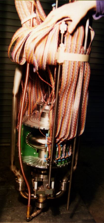
With this in mind, the
SRF Group at Cornell established a program to test the HPP procedure on 3 GHz niobium accelerator cavities (1-cell, 2-cell, and 9-cell). A test apparatus was constructed which was capable of delivering up to
200 kW incident power, with pulse length up to
2 msec , and repetition rate of about
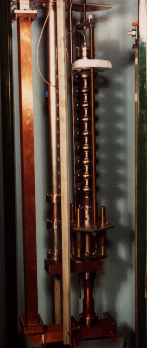
1 Hz . The test stand (shown at left - click on it for a larger copy of the same picture) was further constructed with a variable input coupler, such that input coupler external Q was variable between 1e5 (necessary for HPP), and 1e10 (for low power measurement of the cavities before and after HPP) without a break in the cavity vacuum.
Did it Work?
As a matter of fact, it did. (
Whew, said Joel, while writing his dissertation). Achievable accelerating gradients were 50-80% higher following HPP than before HPP. The 2-cell cavity reached a continuous wave (CW) peak electric field of 100 MV/m, the highest surface field reached to date in an accelerating cavity. Furthermore, the 9-cell cavities reached on average 15-20 MV/m accelerating gradient, as opposed to the 8-14 MV/m attainable without HPP.
Based on
thermometry studies and microscopic investigation of RF surfaces following HPP, processing is believed to be an explosive event, wherein the local heating of the emitter (due to the emission current) is high enough that a micron-sized region will melt and/or explode. Following this explosive event, the emission current will generally be reduced or eliminated.
A more complete description of this phenomena can be found in the Ph.D. dissertation
High Power RF Processing Studies of 3 GHz Niobium Accelerator Cavities , by Joel Graber (1993, Cornell University).
A description can also be found in two articles in
Nuclear Instruments and Methods in Physics Research A , A 350 (1994) 572-581, and A 350 (1994) 582-594. These papers are also available on line as
TESLA Reports, numbers
93-45 and
93-46, respectively.