Visible Light Beam Size Monitor
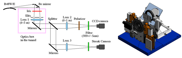
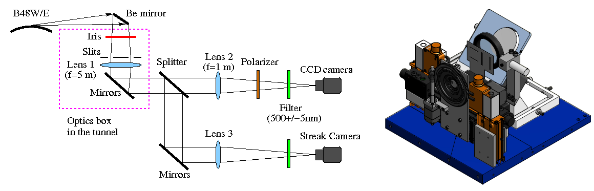
Schematic layout of vBSM setup (left) and CAD drawing of optics box in the tunnel (right).
The visible light beam size monitor (
vBSM) is an instrument that utilizes visible light synchrotron radiation (SR) from a bending magnet to measure the beam sizes in all three dimensions: horizontal, vertical, and longitudinal. Two vBSMs at
CesrTA are located at the north area of storage ring and placed symmetrically at east and west ends of the north straight in order to image visible SR from the counter rotating electron and positron beams respectively. The figure above (left) shows the schematic layout of the instrument optics that transports the SR from the CESR accelerator to a radiation-safe experimental hall. The distance from source to Lens 1 is ~6 m while the total light path from source to CCD camera is ~27 m.
The vBSM employs a double-slit interferometer to measure both the horizontal and vertical beam sizes over a wide range of single bunch currents (0.1 ~ 10 mA). By varying the separation of the slits, beam sizes ranging from 50 to 500 μm can be measured with a resolution of approximately 5 μm. The figure below shows the interference pattern from a horizontal beam size measurement. When rotating the double slits away from SR beam path, direct imaging can be employed to measure larger beam size (> 500 μm). Besides the interferometry, an alternative method for measuring small vertical beam sizes is to image the π-polarized component of SR (
1,
2). To measure the bunch length (longitudinal beam dimension), a beam splitter is inserted to direct a fraction of light into a
streak camera setup.
The vBSMs at CESR-TA have been successfully used in studies of
intra-beam scattering,
fast ion instabilities, emittance and beam tuning.
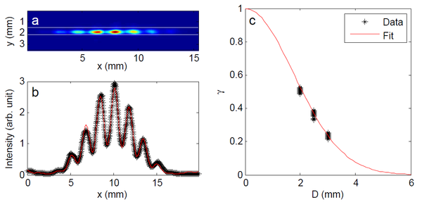
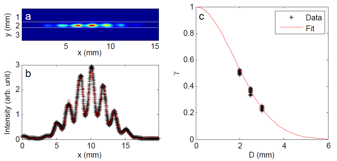
(a) A typical interference pattern of SR using a set of double slits with a separation of
D =2.0mm. (b) The horizontal intensity profile integrated between two white lines. (c) The visibility measured using three different sets of double slits:
D =2.0, 2.5, and 3.0 mm. See
vBSM paper for fitting details.