This page contains the Cornell Assembly Drawings and the DESY Field cage drawings.
2008-04-09 Status of Endplate-FieldCage interface
.......
go to the page of Assembly Configurations
for for an updated drawing of the 3GEMG configuration
-
What is large diameter of plug for the field cage trim contact?
It is within the clearance, 16mm diameter.
2008-02-21 Status of Endplate-FieldCage interface
.......
go to the page of Assembly Configurations
for more details of both 3GEMG and Micromegas assemblies
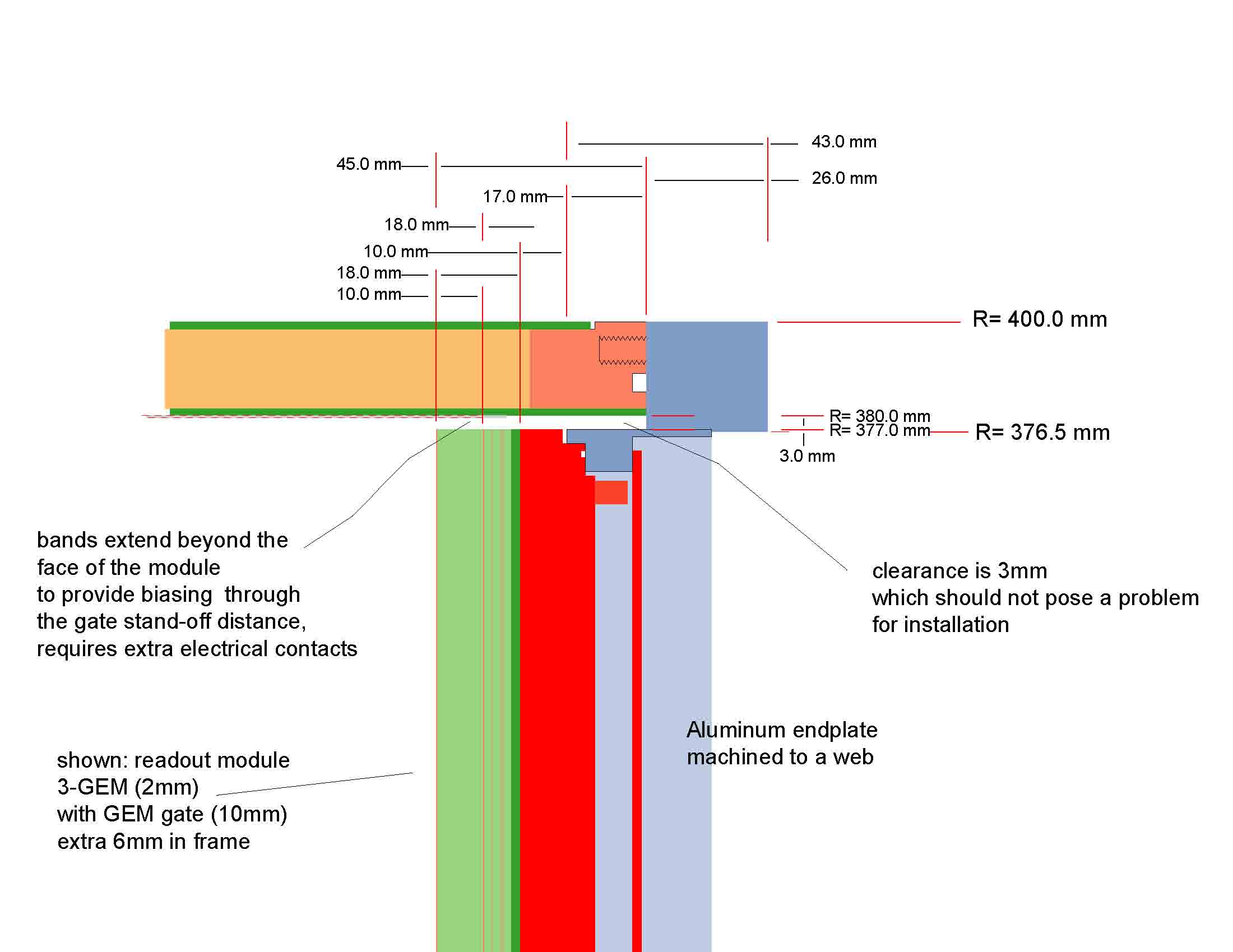
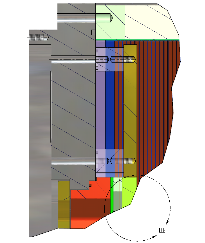
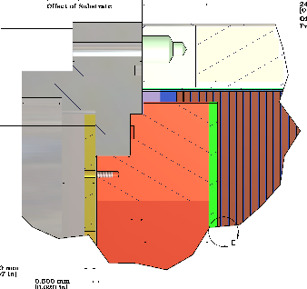
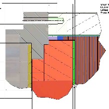
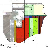
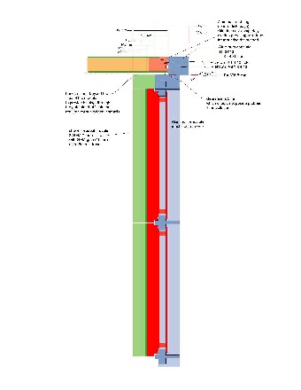
The entry posted on 2008-02-21 shows the assembly for 3GEM with Gate.
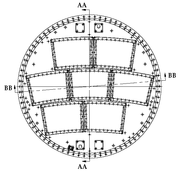
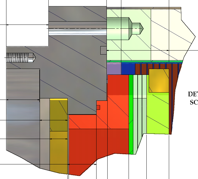
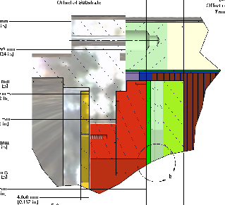
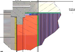
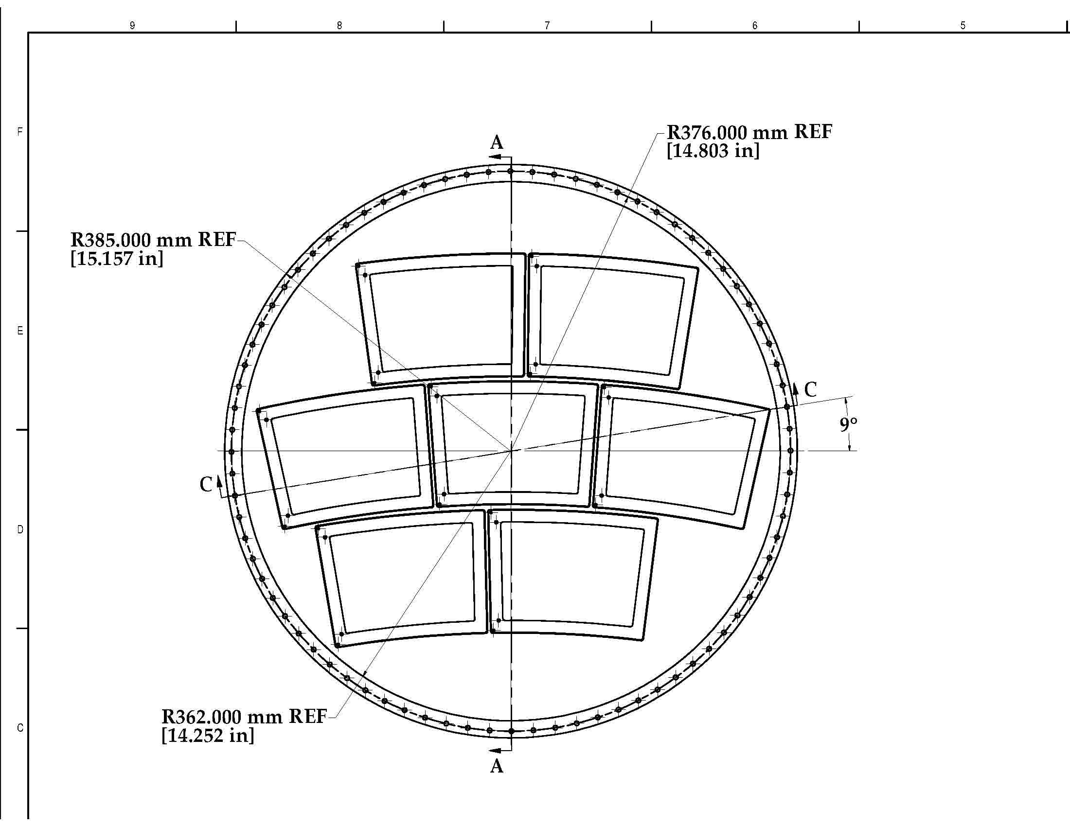
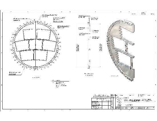
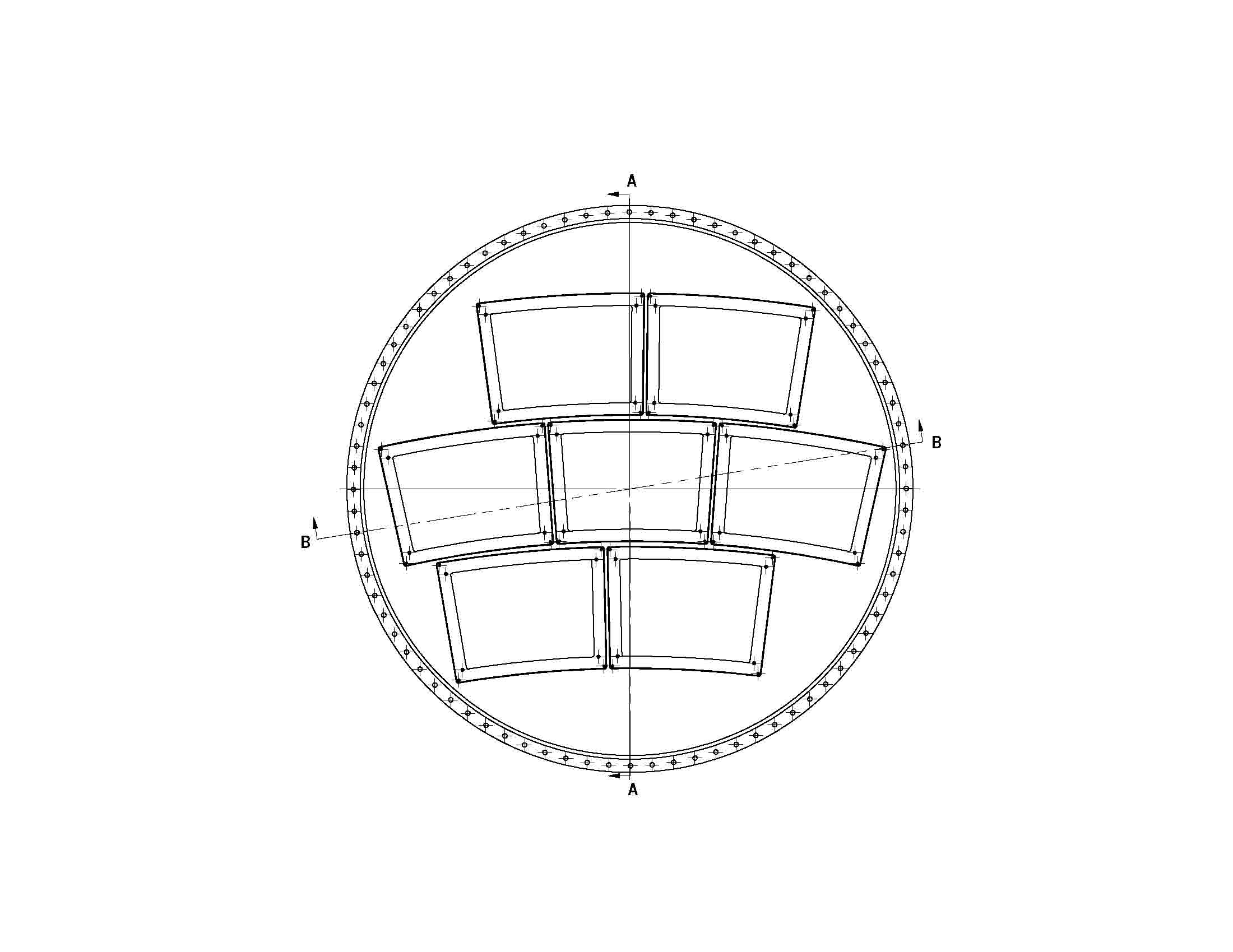
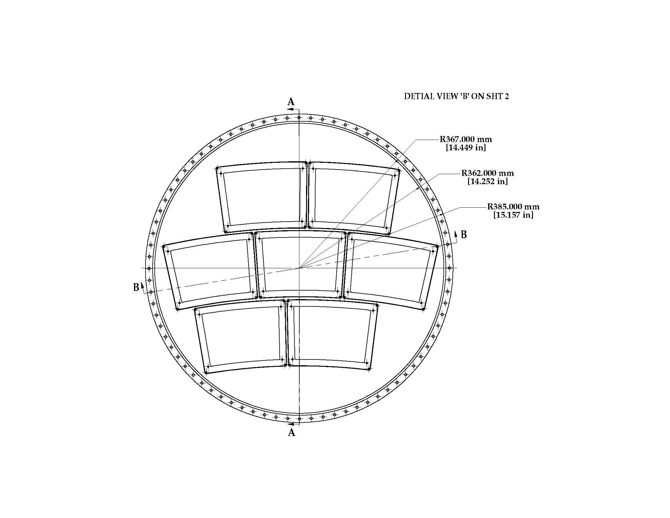
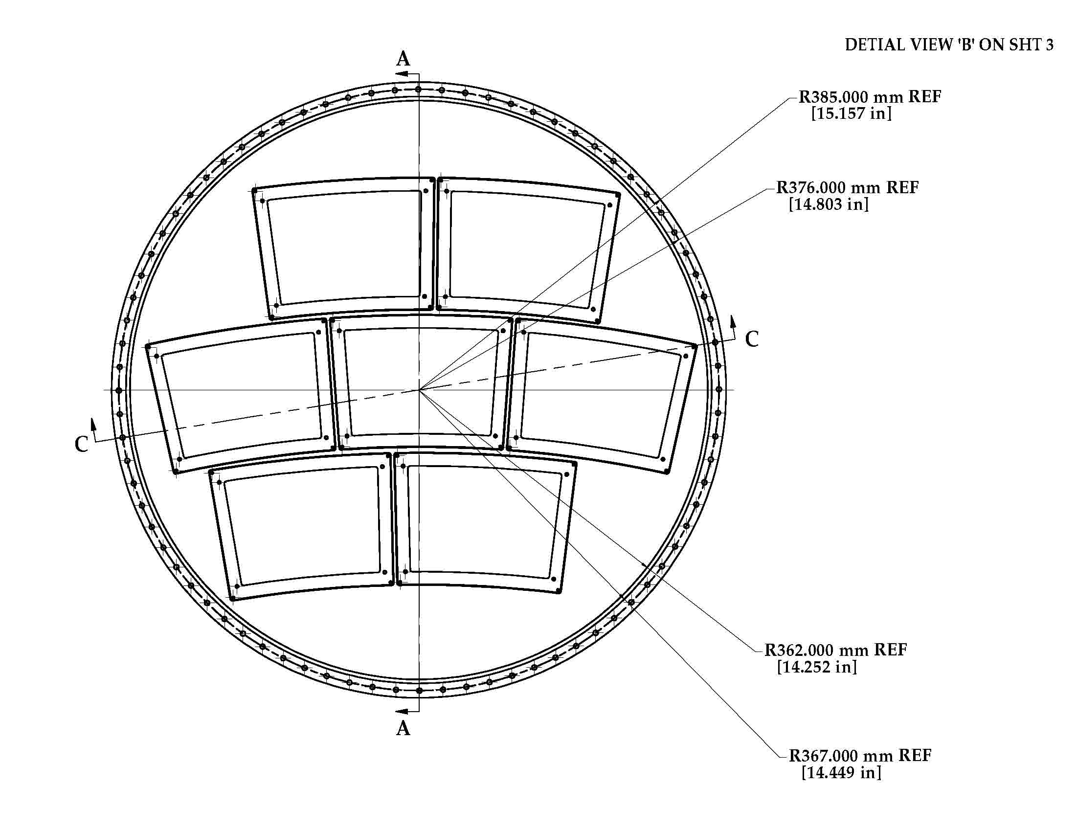
The center drawing shows the section BB. This is through a bolt hole and shows the 3GEMG module.
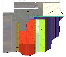
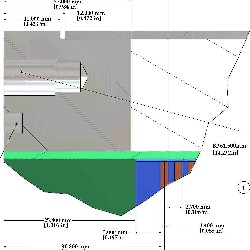
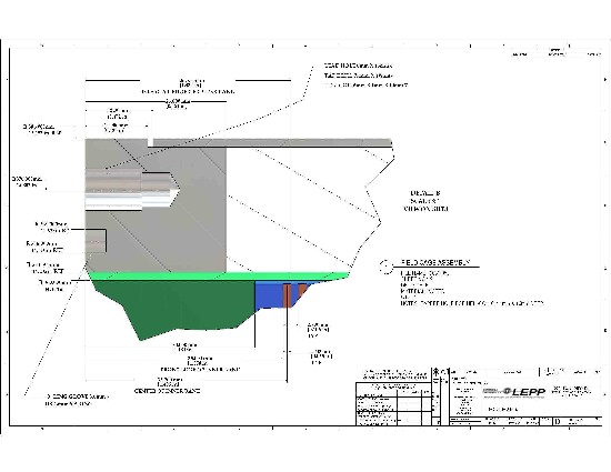
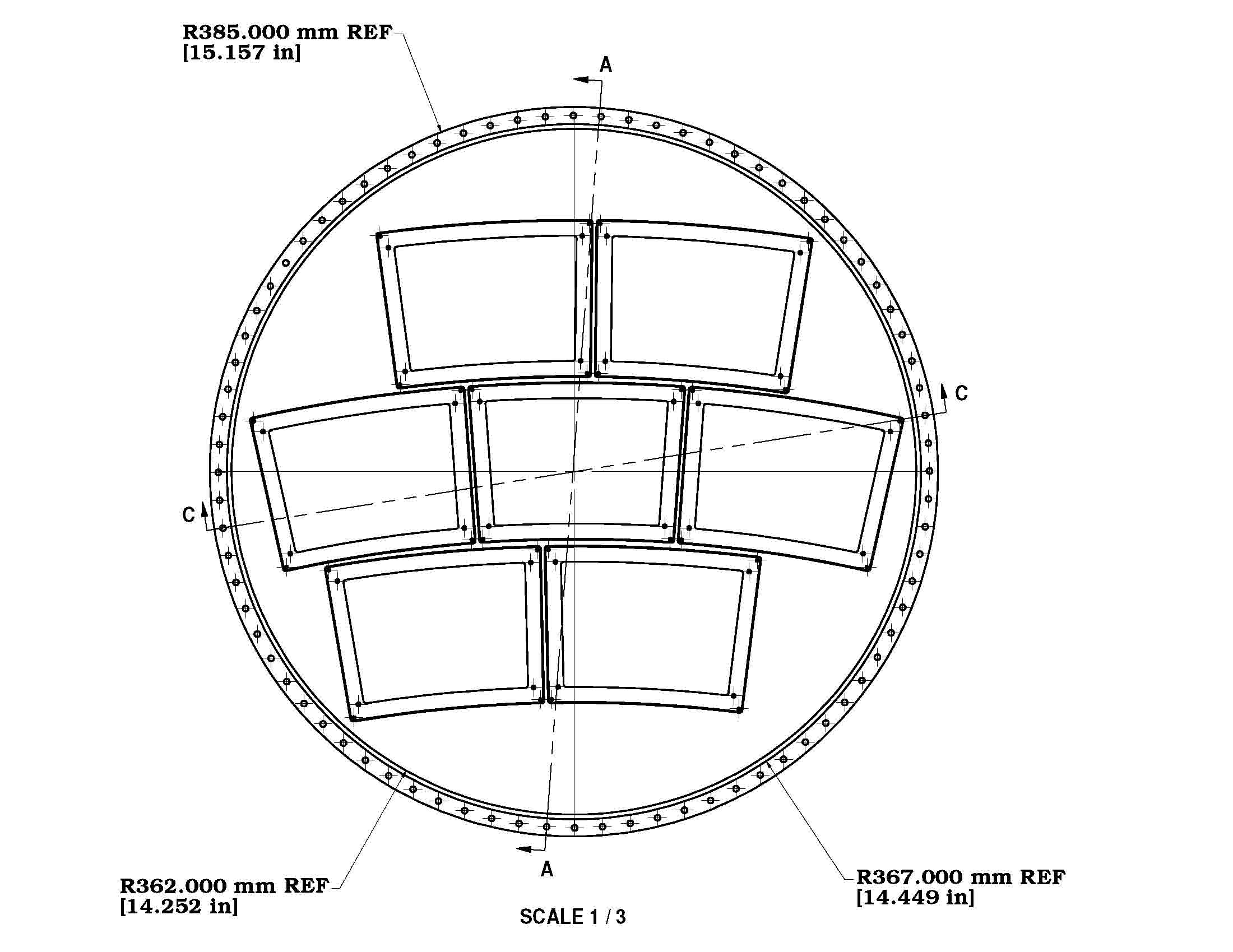
The drawing on the right shows the section at AA (vertical). This is through the dowel hole (on the top) shows the postion of the field cage termination.
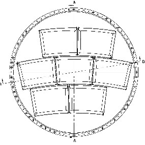
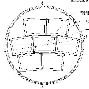
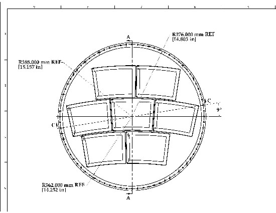
The drawing on the left shows the definition of the sections.
def. section BB and AA(png)
 ...section BB(pdf)
 ...section AA(pdf)
2008-01-29 Status of Endplate-FieldCage interface
.......
go to the page of Assembly Configurations
for more details of both 3GEMG and Micromegas assemblies
The entry posted on 2008-01-29 shows the assembly for Micromegas(without gate).
This is identical to drawings posted 2008-01-07.
-
The only unresolved issue is the routing of the field cage trim band potentials.
-
For Peter's plan of 2008-01-30, what is large diameter of plug (<18mm ?).
(and these are not the "fun holes"; they are "dowel holes".)
The drawing on the right shows the section at AA (vertical). This shows the postion of the field cage termination.
def. section CC and AA(jpg)
 ...section CC(pdf)
 ...section AA(pdf)
2008-01-07 Micromegas modules, Endplate, Field cage Assembly
The entries posted on 2008-01-07 show updates of the assembly for Micromegas(without gate).
This drawing supercedes 2007-12-04.
-
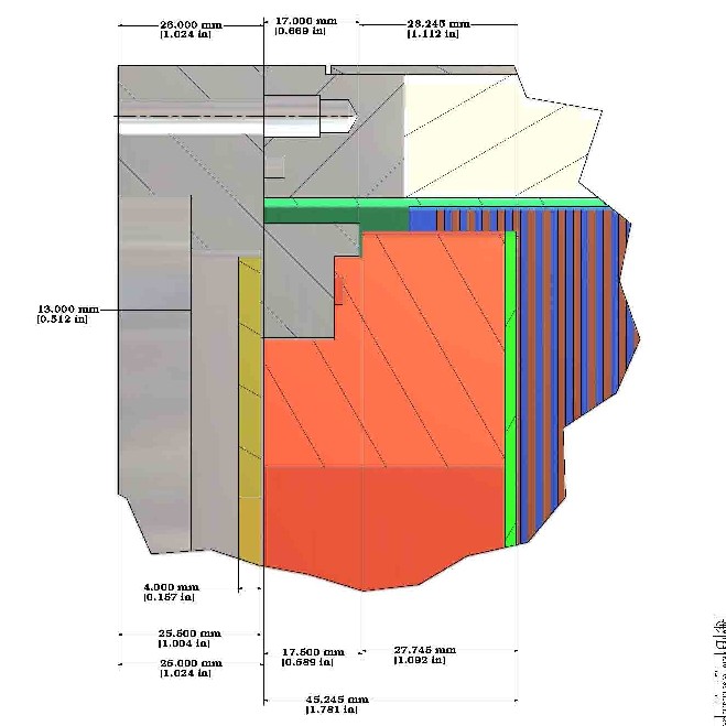
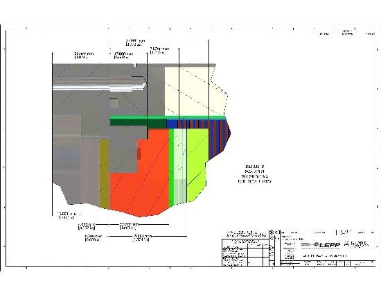
The assembly drawings (center and right) are details at section-CC and section-AA (defined on the left).
-
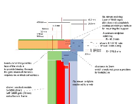
The location of the band substrate, relative to the flange, has been set at 6.6mm. This places the center of the 6th band at 28mm from the flange.
-
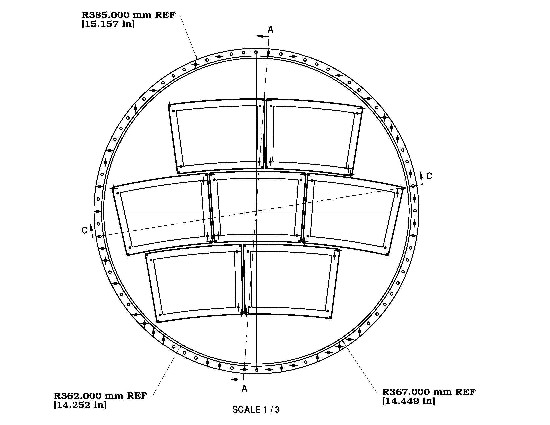
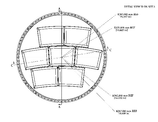
The bolt circle radius is 375mm consistant with the specification of the field cage.
There are 40 holes and one of the bolt holes is located at zero degrees.
-
The field cage flange insert is shown with OD=10mm.
-
The o-ring groove outer radius is 367mm, width is 3.65mm, depth is 2.75 mm, for a 3.55mm o-ring with 4-surface contact, as proposed 2007-12-07.
The drawing on the right shows the section at AA (vertical). This shows the postion of the field cage termination.
These comments are specific to the Micromegas and have not changed since 2007-12-04.
(The 3GEMG drawing update is not yet complete.)
-
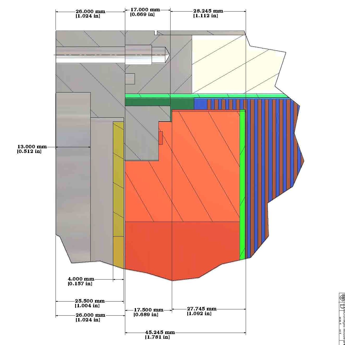
Dimensions for the Micromegas "back frame" are shown in the assembly.
-
The overall length of the "back frame" is 41.8mm (shown in the assembly).
This is as it is being constructed.
The pad board has thickness 3.2mm.
-
The front face of the pad board is at 28mm relative to the surface of the field cage flange.
(shown in the assembly)
def. section CC and AA(jpg)
...section CC(pdf)
...section AA(pdf)
2007-12-04 Micromegas modules, Endplate, Field cage Assembly
The two entries posted on 2007-12-04 show updates of the assemblies for both 3GEM+Gate and Micromegas(without gate). Comments relevant for both configurations are:
-
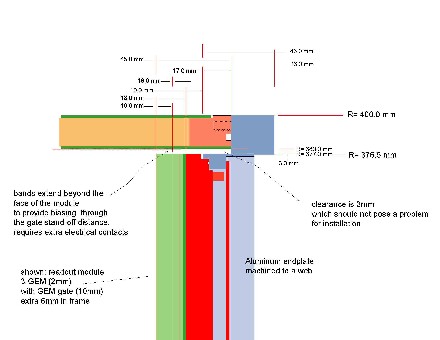
The assembly drawing (on the right) is a detail at section-CC (defined on the left).
-
The location of the band substrate, relative to the flange, has been set at 6.6mm. This places the center of the 6th band at 28mm from the flange.
-
The o-ring groove outer radius is 369mm, width is 3.65mm, depth is 2.75 mm, for a 3.55mm o-ring with 4-surface contact.
-
The bolt circle radius is 375mm consistant with the specification of the field cage.
There are 40 holes and one of the bolt holes is located at zero degrees.
-
The field cage flange insert is shown with OD=10mm.
This comes too close to the o-ring.
This drawing shows an assembly of the Micromegas modules, Endplate, and Field cage.
This drawing supercedes 2007-10-05.
-
Dimensions for the Micromegas "back frame" are shown in the assembly.
-
The overall length of the "back frame" is 41.8mm (shown in the assembly).
This is as it is being constructed.
The pad board has thickness 3.2mm.
-
The front face of the pad board is at 28mm relative to the surface of the field cage flange.
(shown in the assembly)
definition of section-CC(jpg)
...........The Assembly Drawing(pdf)
2007-12-04 3GEM+Gate modules, Endplate, Field cage Assembly
This drawing shows an assembly of the 3GEM+Gate modules, Endplate, and Field cage.
This drawing supercedes 2007-10-05.
-
Dimensions for the 3GEM+Gate "back frame" are shown in the assembly.
-
The overall length of the "back frame" is 27mm (shown in the assembly).
This is as it is being constructed.
The dimensions of the 3GEMG "back frame" are unchanged since 2007-08-07.
-
The front face of the gate is at 28mm relative to the surface of the field cage flange
(shown in the assembly).
definition of section-CC(jpg)
 ...........The Assembly Drawing(pdf)
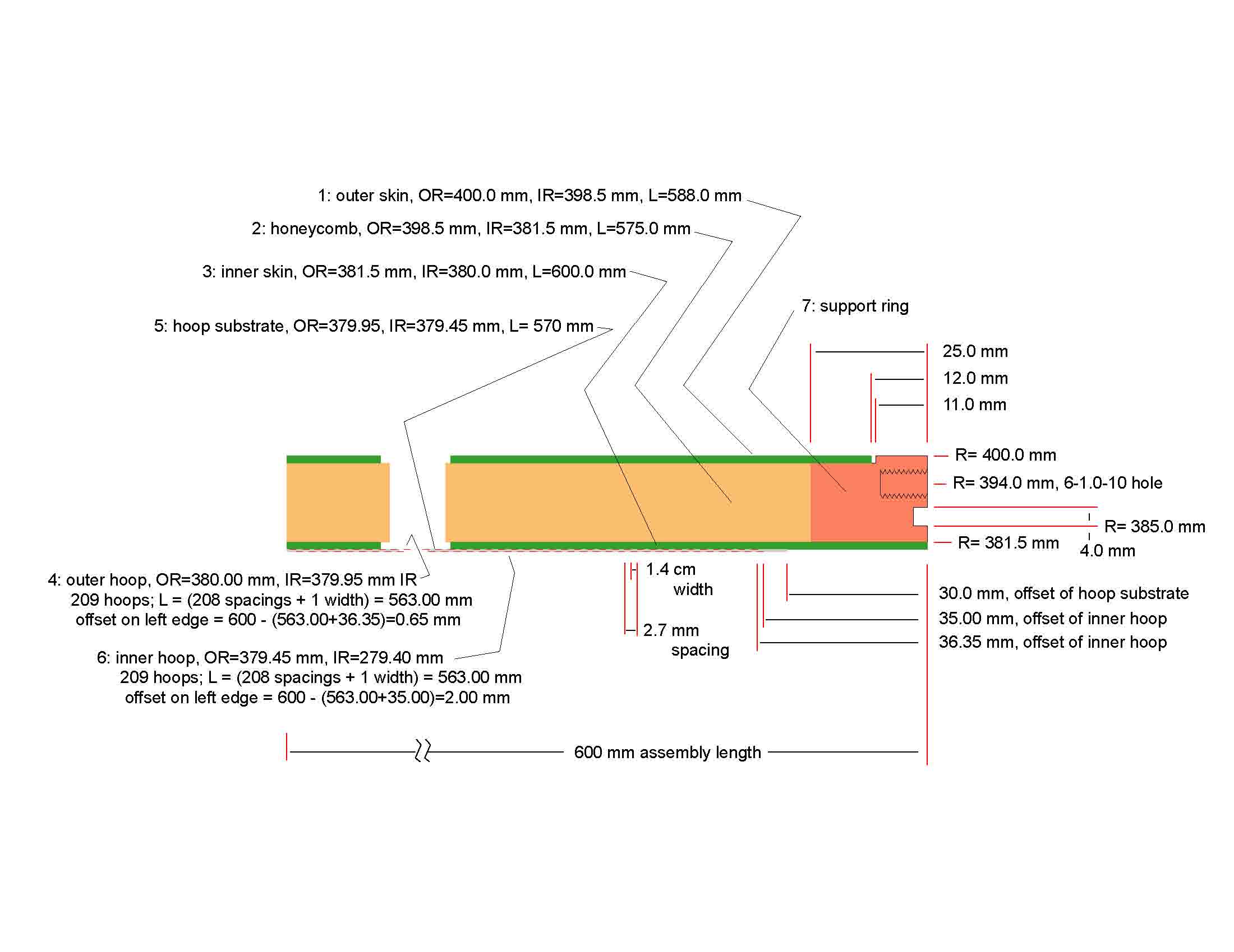
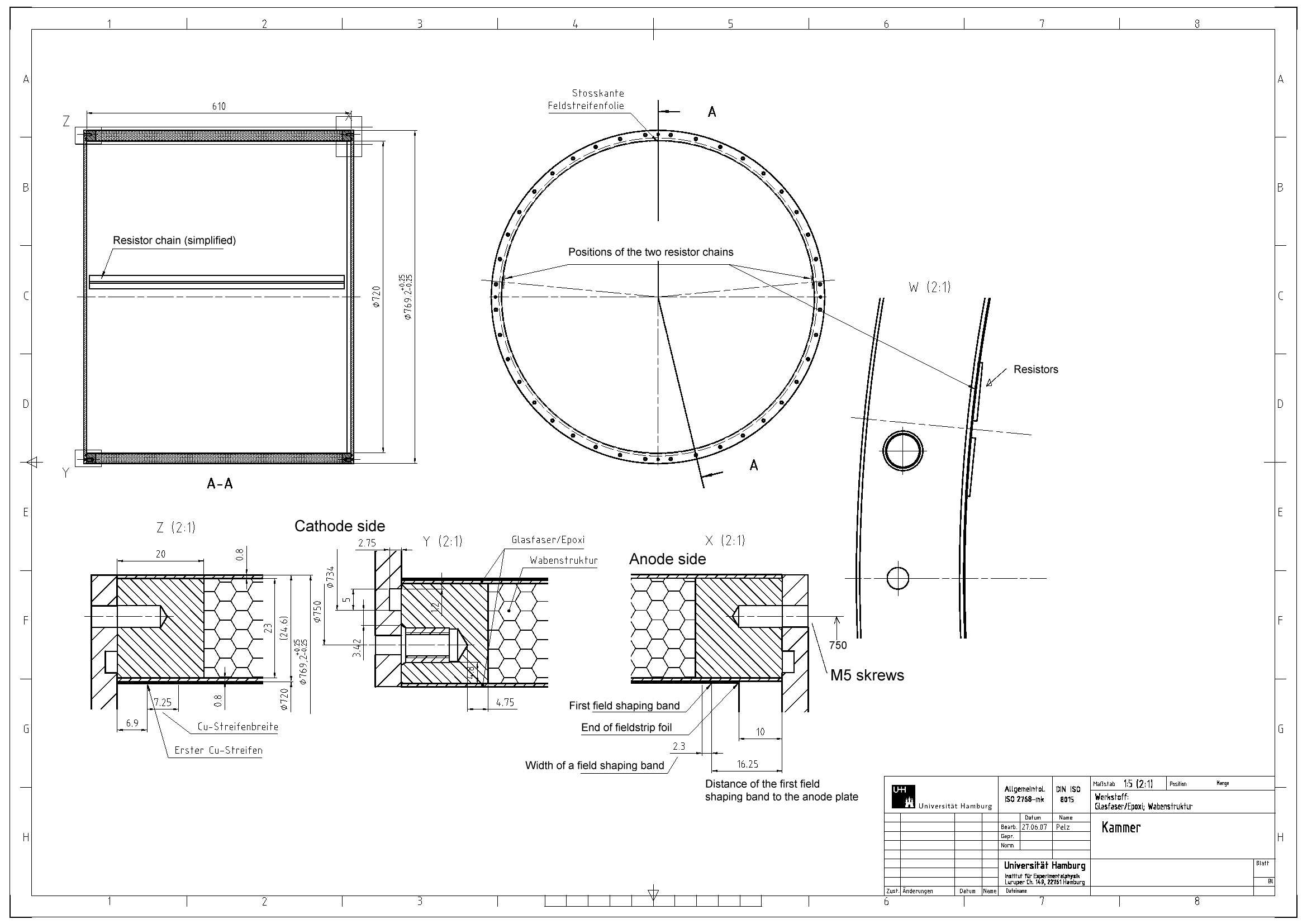
2007-11-19 Field cage drawing from DESY
This is the field cage drawing received from DESY 2007-11-09, dated 2007-11-14.
- The field cage outer radius is 384.0mm.
This is a change from 384.6 in the drawing dated 2007-06-07. The endplate is 385.0mm.
OK
- The field cage inner radius for the structural inner skin is 360.0mm.
(The actual bands are inside of the inner skin.)
The endplate is made to accept a field cage wall radius of 360.0mm with 3mm clearance.
OK
- The bolt circle radius is 375mm; in the endplate drawing this is still 376.
The DESY people had indicated that they are happy with 375mm.
The endplate will be changed to 375mm. This will require only a minor change to the stiffening flange.
- The field cage drawing indicates 5mm screws.
We need to understand the strength of 5mm and 6mm screws.
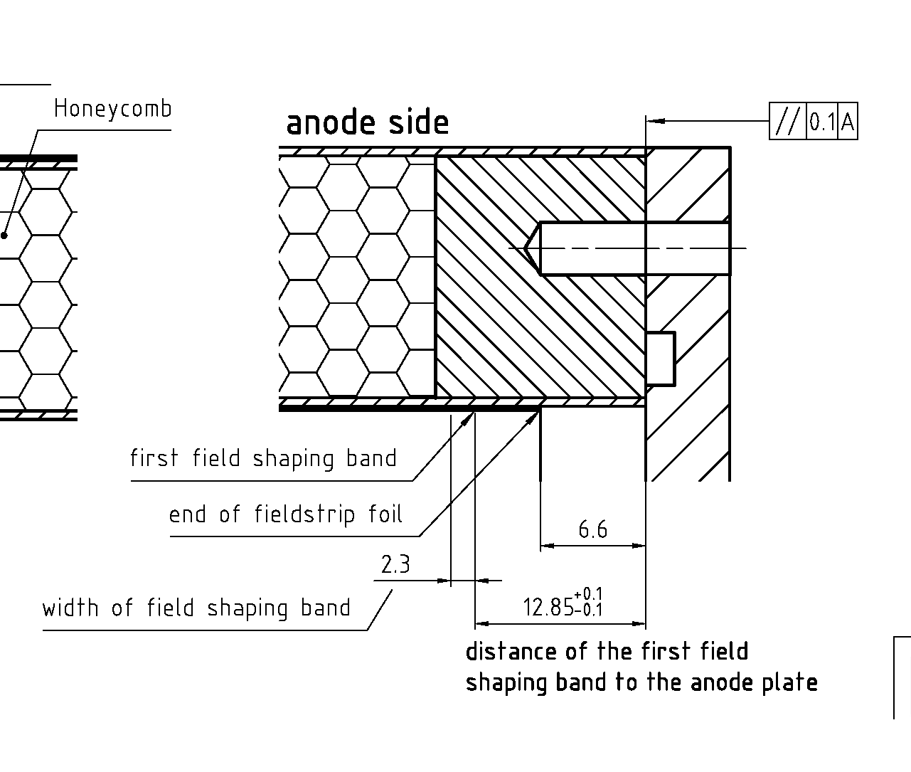
- The bands are 2.3mm width; the pitch is 2.8mm.
The edge of the the first band is located 12.85 from the flange.
Thus, the center of the first band is at 14.0mm from the flange.
-
This will place band centers (inside band row) at the following locations:
(1)14.0, (2)16.8, (3)19.6, (4)22.4, (5)25.2mm, (6)28.0 .
The center of the 5th band at 28.0mm, consistant with the module gemetry.
-
In the DESY drawing, o-ring groove on the cathode side is specified with 4.7mm width and 2.75mm depth.
After compression, the width is 4.58mm (assuming constant cross section and oval shape).
Thus, this groove provides a 2-surface contact.
The outer radius is 369mm; the inner radius is 364.3mm.
-
In the DESY drawing, the o-ring groove on the anode side is not specified.
The endplate specifies a 3.65mm width groove with 2.75mm depth, providing a 4-surface contact.
After compression, the o-ring groove is 98.6% filled (assuming constant cross section).
The outer radius is 369mm; the inner radius is 365.35mm.
the DESY drawing(png)
 (pdf)
(pdf)
2007-10-05 Micromegas modules, Endplate, Field cage Assembly
The two entries posted on 2007-10-05 show updates of the assemblies for both 3GEM+Gate and Micromegas(without gate). Comments relevant for both configurations are:
-
The assembly drawing (on the right) is a detail at section-BB (defined on the left) and replaces the geometry sketches as shown below, 2007-01-17.
-
The endplate is now flat.
There is no step in the endplate between the surface that mates to the field cage and the surface where the modules are mounted.
The field shaping bands in the field cage have been moved to compensate.
-
The location of the band substrate, relative to the flange, has been set at 9.4mm. This places the center of the 5th band at 28mm from the flange.
-
The field cage o-ring has been moved to the endplate.
-
The o-ring groove outer radius is 369mm, width is 3.65mm, depth is 2.75 mm, for a 3.55mm o-ring with 4-surface contact.
-
The bolt hole locations have not changed.
The bolt circle radius is 376mm.
There are 40 holes and one of the bolt holes is located at zero degrees.
(I don't remember if we wanted to change that.)
-
There is an added flange to increase the stiffness of the endplate. The dimensions of this stiffening flange might change after I calculate what is needed to provide a moment of inertial 2x that provided with a simple outer ring, 25mm thick.
This drawing shows an assembly of the Micromegas modules, Endplate, and Field cage.
This drawing supercedes 2007-09-18.
-
Dimensions for the Micromegas "back frame" are shown in the assembly.
-
The overall length of the "back frame" is 42.945mm
.(shown in the assembly)
-
The front face of the Micromegas is at 28mm relative to the surface of the field cage flange.
(shown in the assembly)
definition of section-CC(jpg)
...........The Assembly Drawing(pdf)
2007-10-05 3GEM+Gate modules, Endplate, Field cage Assembly
This drawing shows an assembly of the 3GEM+Gate modules, Endplate, and Field cage.
This drawing supercedes 2007-09-18.
-
Dimensions for the 3GEM+Gate "back frame" are shown in the assembly.
-
The overall length of the "back frame" is 27mm.
.(shown in the assembly)
The dimensions of the "back frame" are unchanged since 2007-08-07.
-
The front face of the gate is at 28mm relative to the surface of the field cage flange.
(shown in the assembly)
definition of section-CC(jpg)
...........The Assembly Drawing(pdf)
2007-09-19 Field cage drawing from DESY
This is the field cage drawing received from DESY 2007-08-09, dated 2007-06-07. Additional information was provided at the WP meeting 2007-09-19.
- The field cage outer radius is 384.6mm; the endplate is 385.0mm.
OK
- The field cage inner radius for the structural inner skin is 360.0mm.
(The actual bands are inside of the inner skin.)
Thus, the wall thickness is 24.6mm.
The endplate is made to accept a 25mm field cage wall with 3mm clearance.
OK
- The bolt circle radius is 375mm; in the endplate drawing this is 376.
The DESY people have indicated that they would prefer a larger radius.
We need an agreement on the bolt circle radius.
- The field cage drawing indicates 5mm screws.
(I will call them "bolts" starting at 8mm.)
We need to understand the strength of 5mm and 6mm screws.
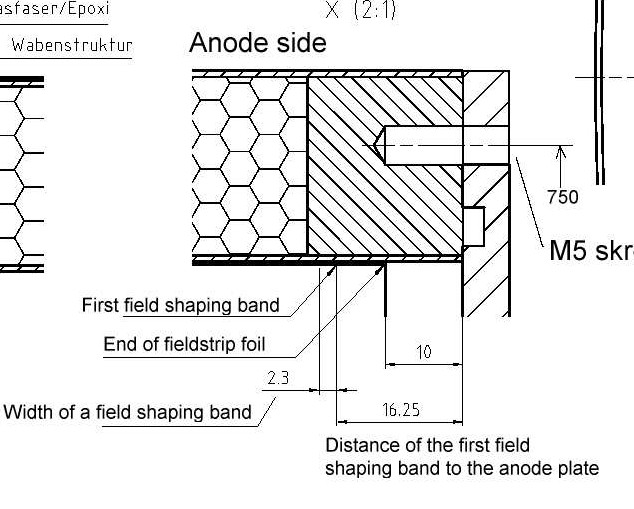
- The bands are now shown with 2.3mm width.
The edge of the substrate is positioned 10mm from the flange while the edge of the first band is 6.25 from the edge of the substrate.
Thus, the edge of the first band is 16.25mm from the flange.
As stated at the 2007-09-19 meeting, the pitch is 2.8mm.
(This is a change from the original information, 2005-12-23, which was 2.7mm.)
Thus, the center of the first band is at 17.4mm from the flange.
We could do this, but...
-
this will place band centers (inside band row) at the following locations:
(1)17.4, (2)20.2, (3)23.0, (4)25.8, (5)28.6mm.
As agreed, 2007-10-03, to place the center of the 5th band at 28.0mm, the first band edge should be moved to 16.8mm.
This 28mm measurement has been in the open since the geometry posting 2006-12-20.
There was some discussion of this value at the meetings 2006-11-22 and 2006-12-20
but I can not find an actual decision on that value.
Thus, an alternative way to achieve alignment would be to add the 0.85mm to the length of the
module back frame, placing the front surface of the module at 28.85mm.
- The drawing indicates a 5mm width oring groove. In a later email, 207-08-20, this was changed to 4.05~4.60mm for a 3.55mm o-ring. This provides a 2-surface contact.
I advocate a 3.60mm width groove with a 4-surface contact.
See 2007-08-21, below.
the DESY drawing(jpg)
 (pdf)
(pdf)
2007-09-18 Micromegas modules, Endplate, Field cage Assembly
The two entries posted on 2007-09-18 show updates of the assemblies for both 3GEM+Gate and Micromegas(without gate). Comments relevant for both configurations are:
-
The assembly drawing (on the right) is a detail at section-CC (defined on the left) and replaces the geometry sketches as shown below, 2007-01-17.
-
The endplate is now flat.
There is no step in the endplate between the surface that mates to the field cage and the surface where the modules are mounted.
The field shaping bands in the field cage have been moved to compensate.
-
The field cage o-ring has been moved to the endplate.
-
The o-ring radial location and dimensions have not changed.
-
The bolt hole locations have not changed.
The bolt circle radius is 376mm.
There are 40 holes and one of the bolt holes is located at zero degrees.
(I don't remember if we wanted to change that.)
-
There is an added flange to increase the stiffness of the endplate. The dimensions of this stiffening flange might change after I calculate what is needed to provide a moment of inertial 2x that provided with a simple outer ring, 25mm thick.
This drawing shows an assembly of the Micromegas modules, Endplate, and Field cage.
This drawing supercedes 2007-08-13.
-
Dimensions for the Micromegas "back frame" are shown in the assembly.
-
The overall length of the "back frame" is 42.945mm
.(shown in the assembly)
-
The front face of the Micromegas is at 28mm relative to the surface of the field cage flange.
(shown in the assembly)
definition of section-CC(jpg)
 ...........The Assembly Drawing(pdf)
2007-09-18 3GEM+Gate modules, Endplate, Field cage Assembly
This drawing shows an assembly of the 3GEM+Gate modules, Endplate, and Field cage.
This drawing supercedes 2007-08-07.
-
Dimensions for the 3GEM+Gate "back frame" are shown in the assembly.
-
The overall length of the "back frame" is 27mm.
.(shown in the assembly)
The dimensions of the "back frame" are unchanged since 2007-08-07.
-
The front face of the gate is at 28mm relative to the surface of the field cage flange.
(shown in the assembly)
definition of section-CC(jpg)
 ...........The Assembly Drawing(pdf)
2007-08-13 Micromegas module, Endplate, Field cage Assembly
The figure shows the Micromegas (without gate) module mounted in the field cage.
This can be compared to the 3GEM+Gate, 2007-08-07.
Note that the module backframe (the "red thing") extends further into the field cage
to place the face of the Micromegas at the same location as in the case of 3GEM+Gate.
2007-08-07 Field cage drawing
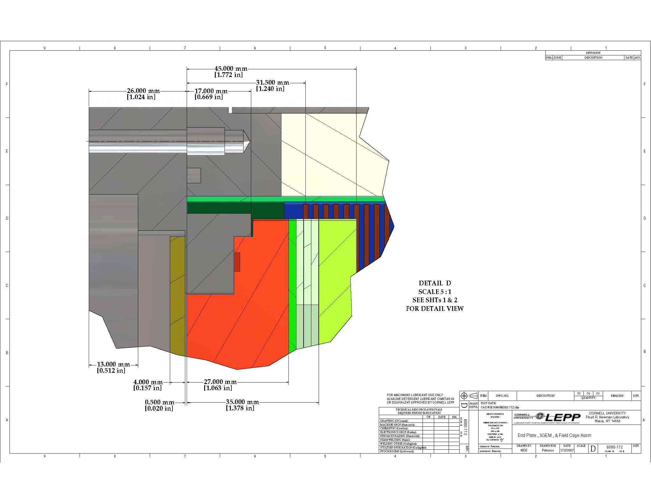
My Field Cage drawing has been updated from 2007-07-03. The first field shaping band is centered at 31.5mm from the flange (was 35.7mm). The 6th inner field band starts at 45.0mm from the flange and is aligned with the face of the detector module. All points listed on on 2007-07-03 still must be resolved.
... the the field cage drawing (pdf)
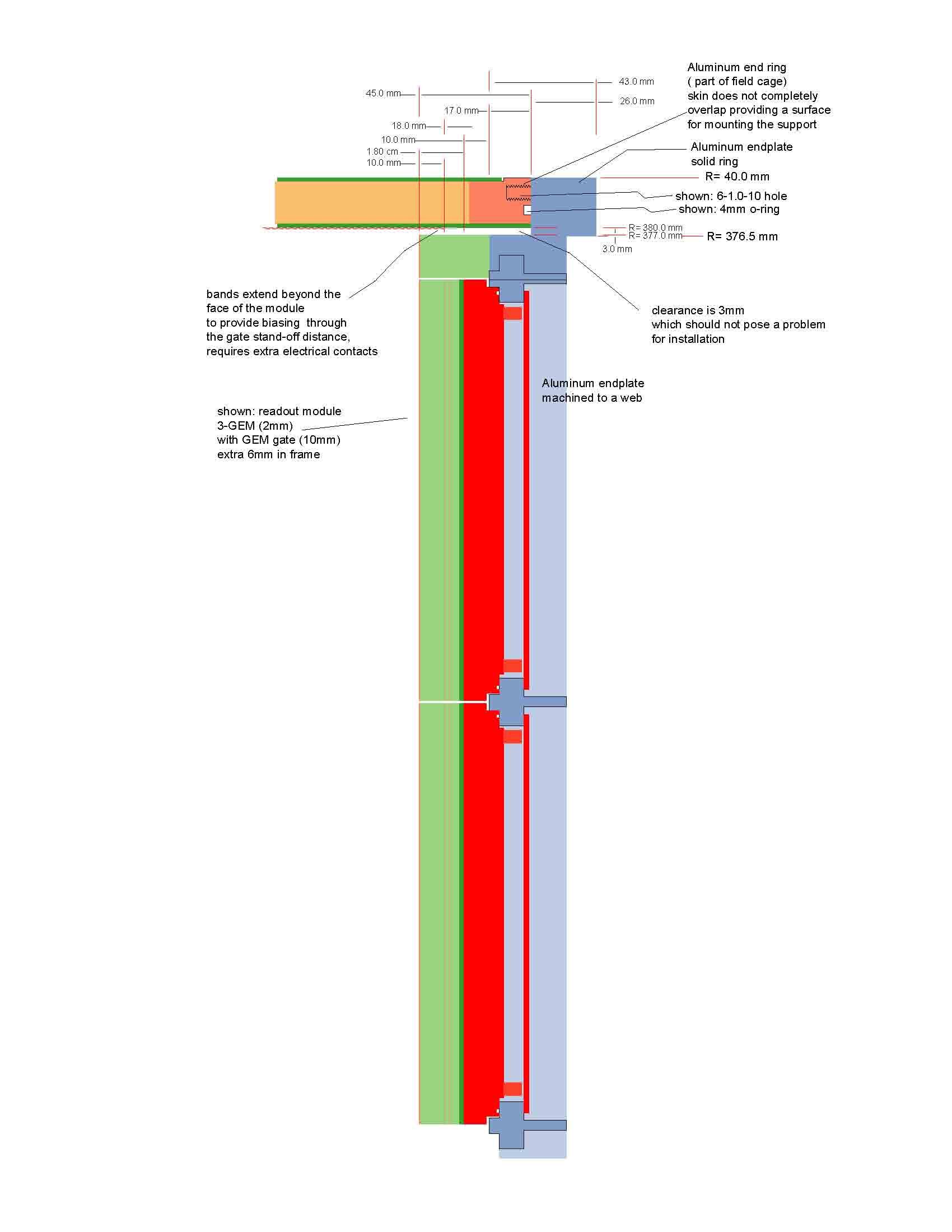
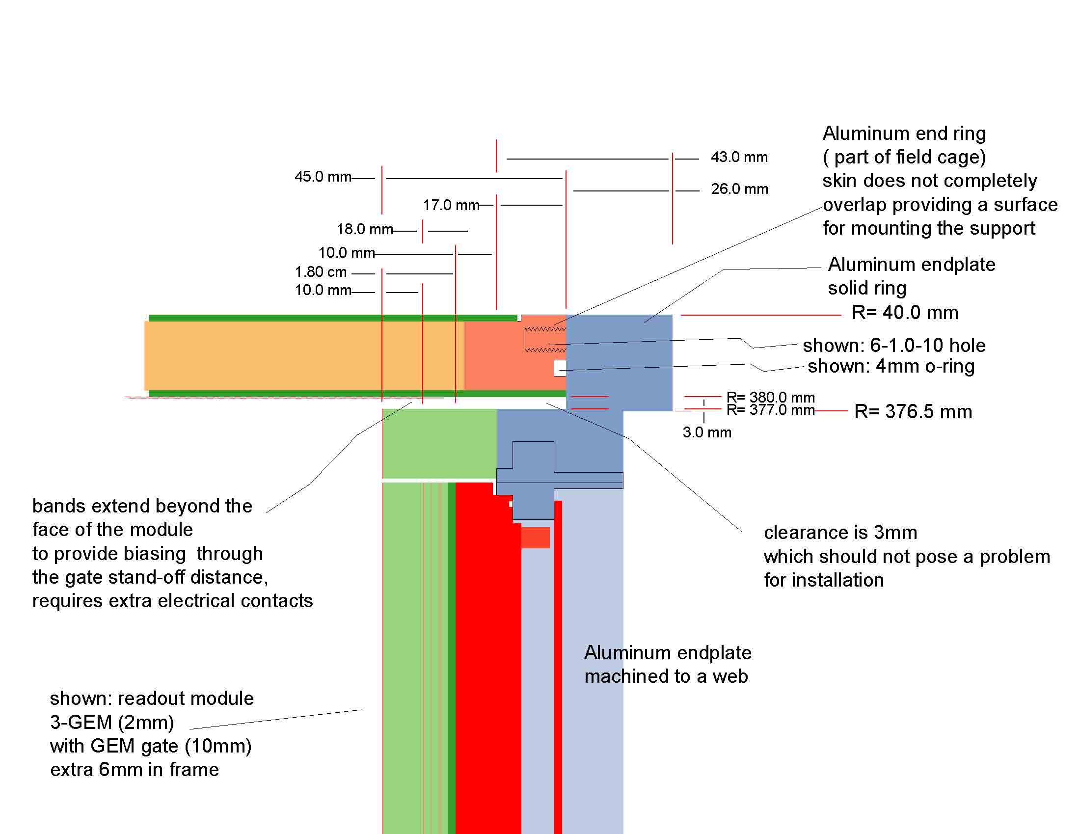
2007-08-07 3GEMG module, Endplate, Field cage Assembly
This new drawing shows an assembly of the Endplate, Modules, and Field cage. This drawing is a detail at section-CC and replaces the geometry sketches as shown below, 2007-01-17.
This is one plan for mating the field cage and the modules to position the face of the module at the center of one of the field cage bands and to locate extra bands beyond the end of the drift volume. The design can be changed after we agree on the distance of the bands from the edge of the field cage flange. This will be followed by adjusting the step in the endplate from the same surface (currently 17mm) for the desired alignment to the field cage bands.
definition of section-CC(jpg)
 (pdf)
...........The Assembly Drawing(jpg)
(pdf)
...........The Assembly Drawing(jpg)
 (pdf)
(pdf)
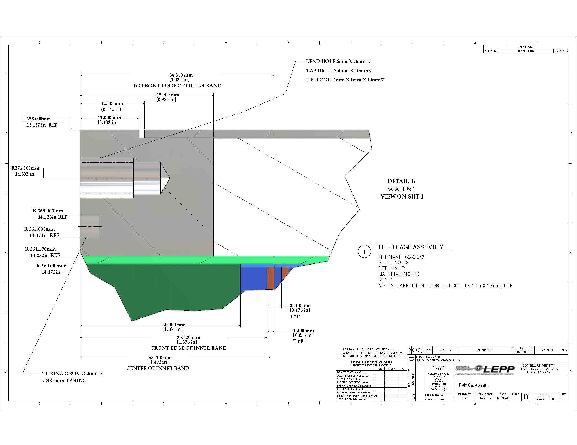
2007-07-03 Field cage drawing
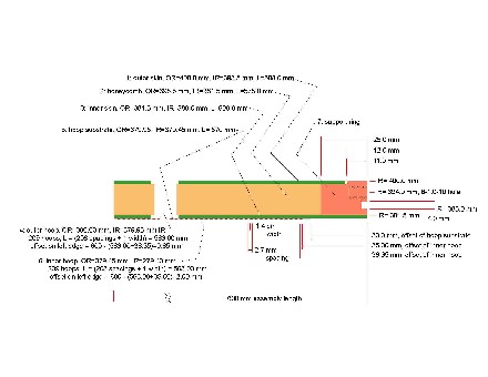
This shows a schematic of a field cage assembly with some dimensions as discussed at DESY 20070604.
-
The physical size is OD=770mm, wall=25mm, ID=720mm.
-
The bolt is 6mm x 1mm pitch. A Heli-coil is used in the field cage flange. This has outer diameter 7.4mm. (The designation in the drawing, "tap drill" is incorrect; this is the outer diameter of the Heli-coil.)
There are other dimensions which are specified in the schematic with only temporary values. For each of these, we must come to an agreement.
-
The bolt circle radius is specified at 376mm.
-
The o-ring is located in the field cage flange, with an inner radius of 365mm and groove width of 4mm. This first decision is whether to place the o-ring in the field cage flange or in the endplate.
Then we can discuss the o-ring cross-section and radial location.
-
The first field shaping band starts at 35mm relative to the edge of the flange that mates to the endplate.
This is consistant with the geometry shown below, 2007-01-17.
In that geometry, the step in the endplate
(from the field cage mounting surface
to the readout module mounting surface)
is 17mm.
This is the same step shown in the endplate drawing below, 2007-07-03.
The agreed distance
(from the readout module mounting surface
to the front surface of a module)
is 28mm.
Thus, the distance
(from the field cage mounting surface
to the front surface of a module)
is 45mm.
With the first field shaping band starting at 35mm,
the center of the 9th band is at 44.9mm and nearly aligns with the front surface of the module.
We must come to an agreement on the location of the first band,
which defines the field correction beyond the face of the module,
and of the band
that defines the end of the drift field.
 pdf
pdf
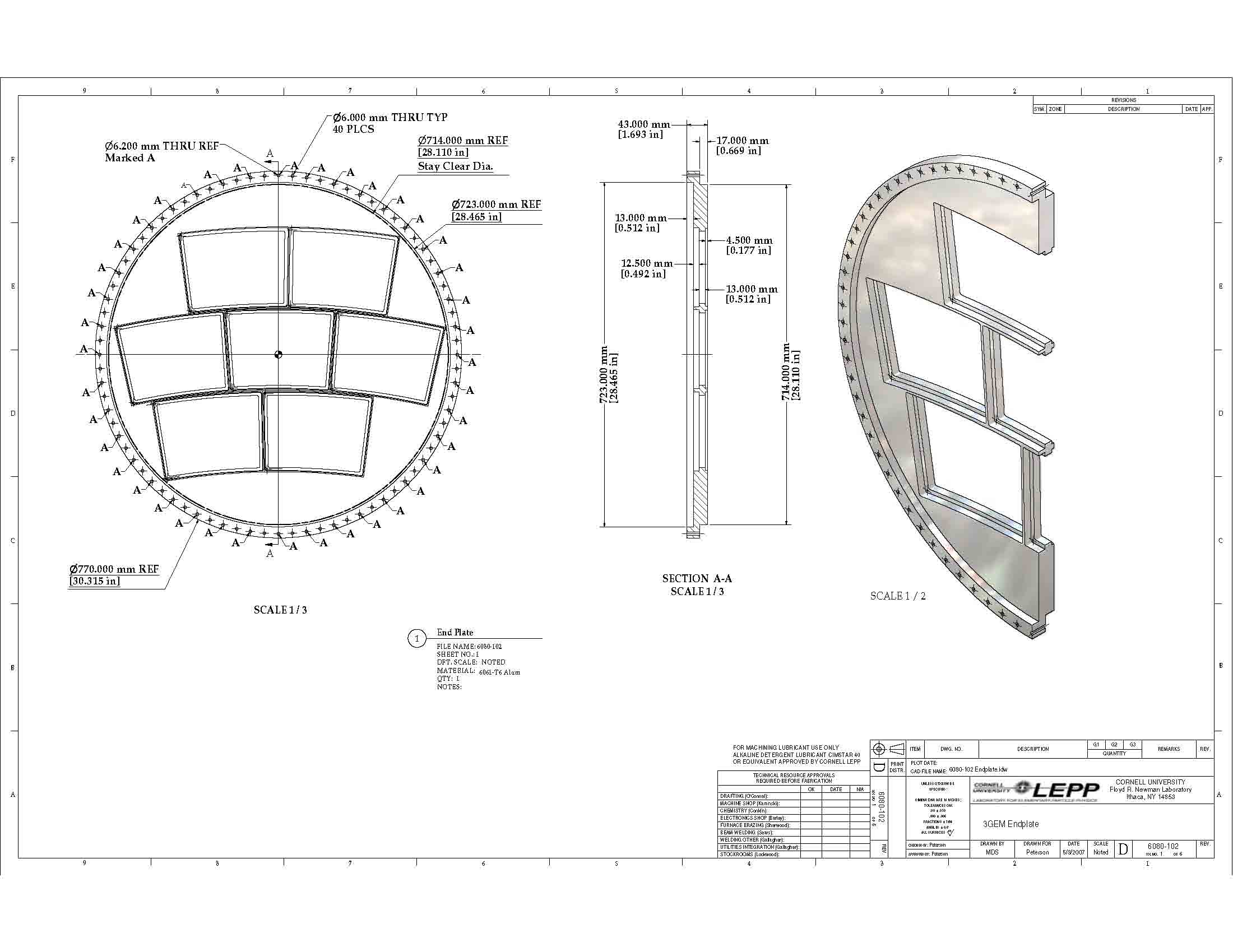
2007-07-03 Endplate drawing: change to 25mm field cage wall
This is an update of the endplate drawing consistent with fieldcage OD=770mm, field cage wall=25mm, ID=720mm.
The inserted diameter and stay clear are both 714mm.
The step in the endplate
(from the field cage mounting surface
to the readout module mounting surface)
is unchanged at 17mm.
This can be changed after defining the distance
(from the field cage edge
to the field shaping band)
that defines the end of the drift length.
(This drawing is updated, from 2007-06-25, with improved font size.)
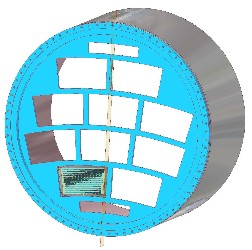
The weight of the endplate, as shown in the drawing below, can be estimated as follows.
-
The outer flange, outside of ID=714mm has volume 1565cm^3.
-
The solid disc with OD=714mm, thickness=30mm, has volume 12011cm^3.
-
The total volume for 7 openings is 7667 cm^3
(approximating the opening as a trapezoid but carefully accounting for the shape of the opening). The volume of the disc with OD=714mm is reduced to 4344cm^3.
-
Thus, the total volume (not accounting for all the mounting holes) is 5919cm^3 and, in aluminum, the "weight" is
16.0kg
or 35.1pounds.
Note that the endplate volume could be reduced by thinning the uninstrumented, odd-shaped, sections. The volume of the disc with OD=714mm could be reduced to about 2000cm^3. In this case, the total volume would be 3565cm^3 and, in aluminum, the weight would be 9.6kg or 21.2pounds.
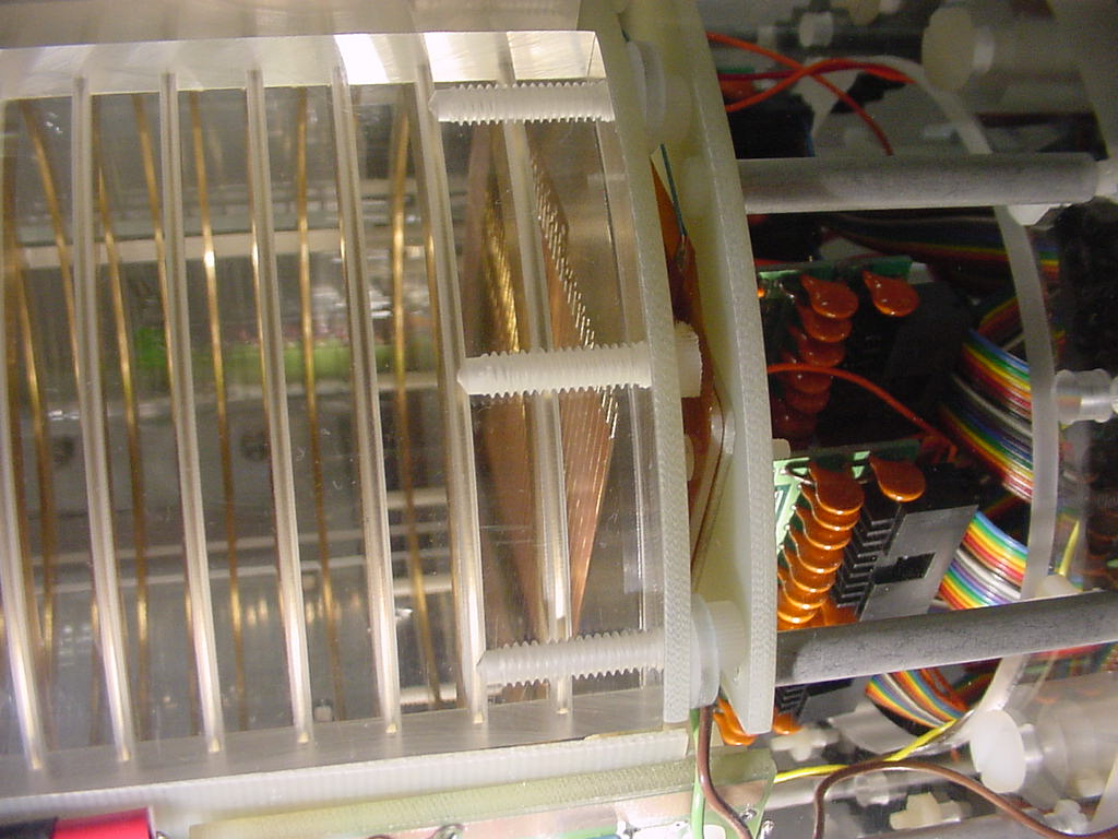
The weight of a module can be estimated from the gas seal test device.
The module picured below, 2007-05-08, and in the drawing, 2007-04-10 (first figure) has a weight of 0.97kg. (This "module" has a perimeter of 939mm while the real modules have a perimeter of 783mm. However, the gas-seal module does not include the mounting bracket and the gas-amplification. Therefore,
1kg
is a fair estimate for the weight of one module.)
The anode sheet which covers the uninstrumented, odd-shaped, sections has an area of 1368cm^2. The mass of this sheet probably will be dominated by a G10 backing. Using 3mm G10 (density=1.9), this weight is about
0.8kg.
 pdf
pdf
2007-01-17 Endplate:Fieldcage:Panel geometry update (EndplateFieldCageGeometry7)
 pdf
pdf
 pdf
pdf
 pdf
pdf
 pdf
pdf
 PRESENTATIONS
 (purdue)
 ...section CC(pdf)
 ...........The Assembly Drawing(pdf)
 (pdf)
(pdf)
 ...........The Assembly Drawing(pdf)
 ...........The Assembly Drawing(pdf)
 (pdf)
...........The Assembly Drawing(jpg)
(pdf)
...........The Assembly Drawing(jpg)
 (pdf)
(pdf)